


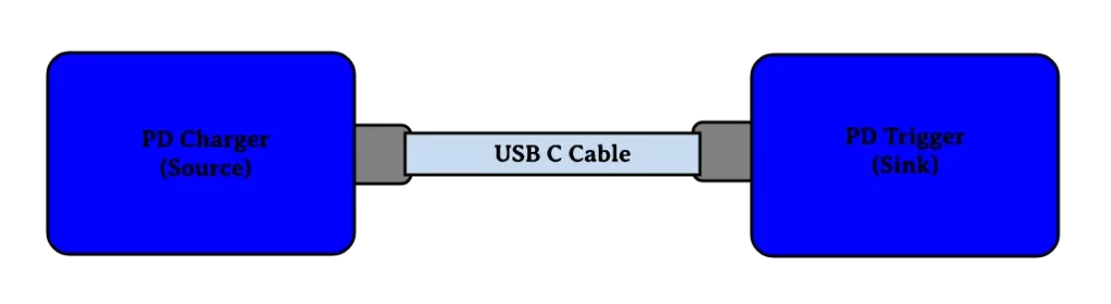
USB has evolved from a data interface capable of supplying limited power to a primary provider of power with a data interface. Today many devices charge or get their power from USB ports contained in laptops, workstations, docking stations, displays, cars, airplanes or even wall sockets. USB has become a ubiquitous power socket for many small devices such as cell phones, tablets, portable speakers, and other hand-held devices. Users need USB to fulfil their requirements not only in terms of data but also to provide power to, or charge, their devices simply, often without the need to load a driver, in order to carry out “traditional” USB functions. The USB Power Delivery (USB PD) Specification enables the maximum functionality of USB by providing more flexible power delivery along with data over a single cable. Its aim is to operate with and build on the existing USB ecosystem. The main blocks in power delivery systems are the source and the sink. The source supplies power over VBUS when the negotiation from the sink controller is successful. The PD systems uses the CC1 and CC2 line in the USB C cable for negotiation.
PD Trigger Modules
Power Delivery (PD) trigger modules are used to get a desired voltage ranging from 5v to 20V from a PD-compatible power supply. PD trigger modules are typically composed of a PD sink controller with various supporting components. One such PD sink controller that is commonly used in PD trigger modules is the FUSB302. In this project, we have used the very same FUSB302 PD controller in our PD trigger module.
Components Required
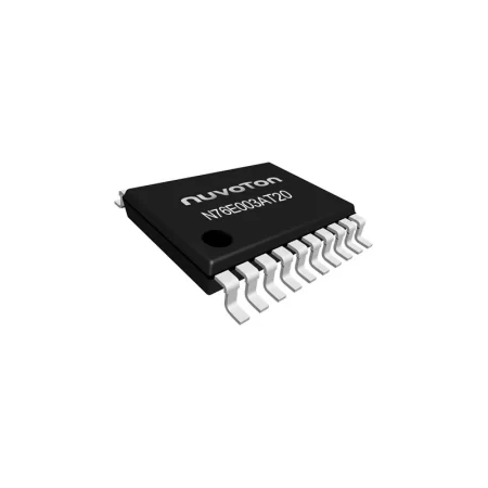
- STM32F030 Microcontroller
- FUSB30 Programmable USB Type‐C Controller with PD
- 3.3V Voltage regulator
- RGB LED
- Tactile Switch
- Resistors
- Capacitors
- USB Type-C connector
- PCB
- Other tools and miscellaneous
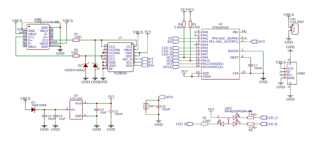
PD Trigger Complete Circuit Diagram
The complete circuit diagram for the PD Trigger is shown below.
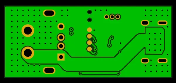
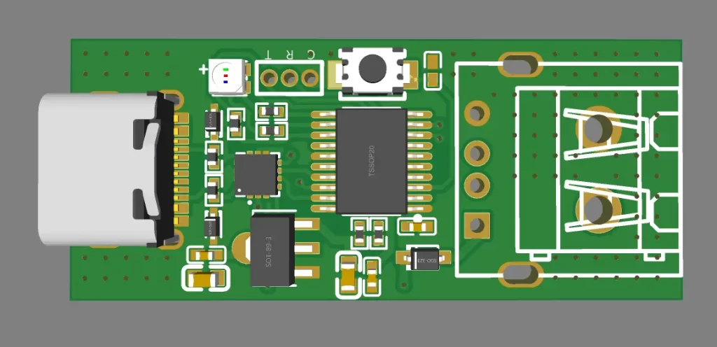
PCB Design
Here is the PCB design for the PD Trigger
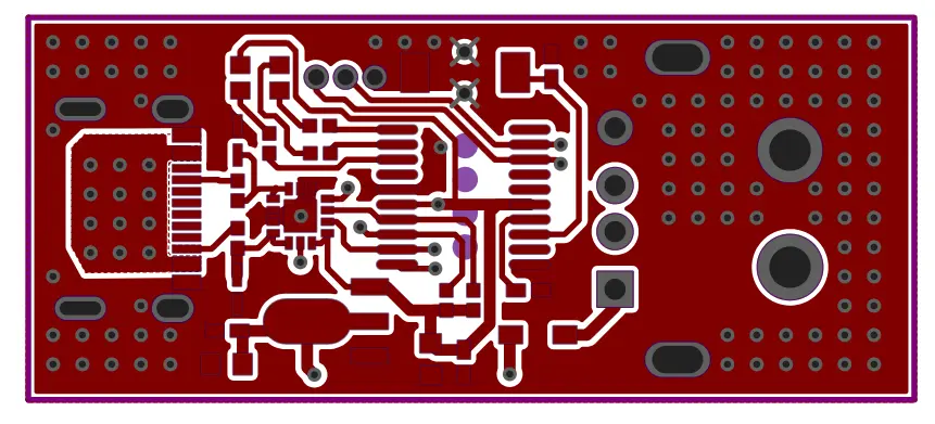
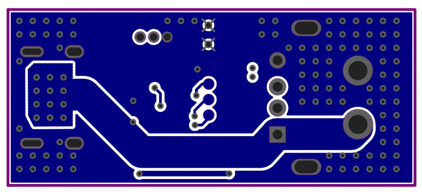
2D View
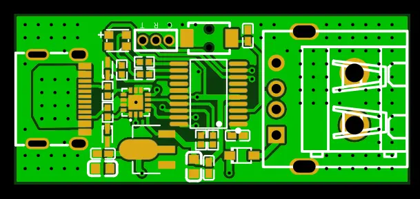
3D View
PCB Fabrication and Assembly
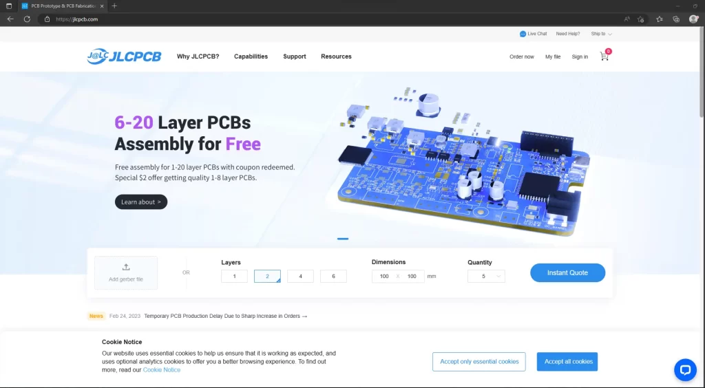
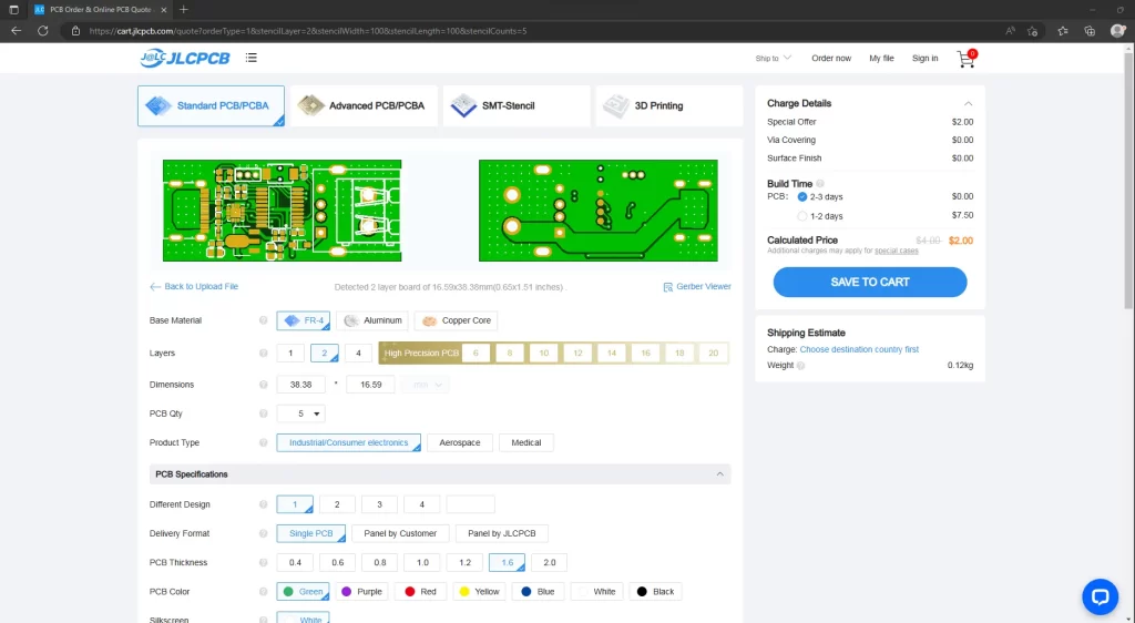
To fabricate the PCBs, I went to JLCPCB.com. JLCPCB offers only $2 for 5 PCBs and their PCB assembly starts from zero dollars. Ordering PCB in JLCPCB is very easy. To order, just click on “Order Now” and select your Gerber file. After that, you can select the colour, thickness, quantity, etc. Here, I choose the black colour. You can choose your favourite PCB colour from plenty of options. Finally, I selected the shipping method and placed the order.
JLCPCB also offers fast and reliable PCB assembly services for your electronic projects. With their state-of-the-art facilities and skilled technicians, they can handle any PCB assembly project, big or small. Whether you need a prototype or a large production run, JLCPCB can provide you with high-quality PCB assembly services at competitive prices. JLCPCB uses only the highest quality components in their PCB assemblies, ensuring that your projects are built to last. They also offer a range of PCB assembly options, including surface mount technology (SMT) and through-hole technology (THT), so you can choose the best option for your project. Their online ordering system makes it easy to get started, and their experienced customer support team is always available to answer any questions you may have. Plus, with their fast turnaround times, you can get your PCB assemblies delivered quickly and on time.
So why wait? Get started with JLCPCB‘s PCB assembly services today and take your electronic projects to the next level!
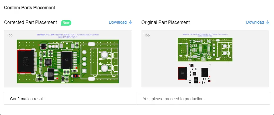
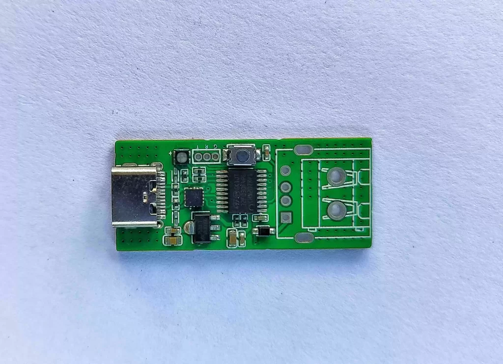
Final Product
Here is the final product. Fully manufactured using JLCPCB. You can see that the PSB is in pristine condition and the assembly quality is Top notch.
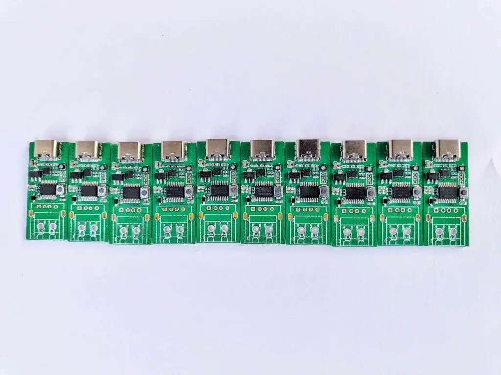
Here are a few more boards from the same production batch. The production quality is consistent across the batch.
Operation
The configuration mode can be activated by plugging in the board while pressing the button. The LED will initially flash fast in cyan colour until the button is released. Then, it keeps flashing to indicate that it is in configuration mode.
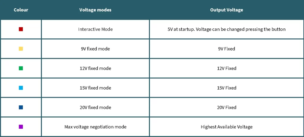
The mode can be selected by pressing the button until the desired voltage or mode (see table above) has been selected. The button must be held down for a longer amount of time until the Light turns off in order to save the setup. The output voltage stays at 5V while in configuration mode. Now just disconnect and reconnect to enter the selected mode.
Notes on Fixed Voltages
Even if a fixed voltage above 5V has been selected and the selected voltage can be provided by the power supply, the supply will initially provide 5V until the target voltage has been successfully negotiated.
If a fixed voltage has been configured and the power supply does not offer it as a fixed voltage but can supply it as part of a PPS (programmable power supply) capability, the PPS capability will be used. This feature enables 12V on a number of power supplies not offering 12V as a fixed voltage.
working video

Leave a comment