


- 1-T 80C51 Central Processing Unit
- MG82F6D17 with 16K Bytes flash ROM
- ISP memory zone could be optioned as 0.5KB/1.0KB~7.5KB
- Flexible IAP size by software configured
- Code protection for flash memory access
- Flash write/erase cycle: 20,000 times
- Flash data retention: 100 years at 25℃
- Default MG82F6D17 Flash space mapping
AP 13.5KB 0000h~35FFh IAP 1.0KB 3600h~39FFh ISP 1.5KB 3A00h~3FFFh
- Data RAM : 1K Bytes
- On-chip 256 bytes scratch-pad RAM
- 768 bytes expanded RAM (XRAM)
- Support page select on XRAM access
- Dual data pointer
- Provide one channel DMA engine
- P2P, M2P, P2M
- Memory target: XRAM
- Peripheral target: UART0, UART1, SPI, TWI0/I2C0, ADC12 & CRC16
- Timer 5 and Timer 6 are used for DMA, but it also can be traded as independent timer when DMA not in use
- Interrupt controller
- 16 sources, four-level-priority interrupt capability
- Three external interrupt inputs, nINT0, nINT1 and nINT2, with glitch filter
- All external interrupts support High/Low level or Rising/Falling edge trigger
- Total 9/10 timers in MG82F6D17
- RTC Timer and WDT Timer
- Timer 0, Timer 1, Timer 2 and Timer 3
- PCA0, Program Counter Array 0
- S0 BRG and S1 BRG
- If Timer 2/3 in split mode, then total 10 timers
- Four 16-bit timer/counters, Timer 0, Timer 1, Timer 2 and Timer 3
- X12 mode and timer clock output function
- Synchronous Run-Enable on all timer (same function on Stop and Reload)
- New 5 operating modes in Timer 2/3 with 8 clock sources and 8 capture sources
- Timer 2/3 can be split to two 8-bit timers
- Clock Count Output (CCO) on T2CKO and T3CKO
- All timers support PWM mode
- One Programmable 16-bit counter/timer Arrays (PCA0) with 8 Compare/PWM modules
- PCA0 has 6 CCP (Capture/Compare/PWM) modules and 2 CP (Compare/PWM) modules
- Reloadable 16-bit base counter to support variable length PWM
- Up to 100MHz clock source from on-chip CKM
- Capture mode, 16-bit software timer mode and High speed output mode
- Buffered capture mode to monitor narrow pulse input
- Variable 8/10/12/16-bit PWM mode, the PCA can be configured to:
Up to 8 channels un-buffered 10/12/16-bit PWM, or Up to 8 channels buffered 2~8-bit PWM, or Up to 4 channels buffered 9~16-bit PWM - PCA0 PWM module 0~5 with dead-time control, break control and central-aligned option
- 8 Inputs Keypad Interrupt
- 12-Bit Single-ended ADC
- Programmable throughput up to 800K sps
- 8 channel external inputs and one channel internal input (IVR/1.4V)
- Support window detect function on ADC result
- Support channel scan mode
- Enhanced UART (S0)
- Framing Error Detection
- Automatic Address Recognition
- Speed improvement mechanism (X2/X4 mode), Max. UART baud rate up to 6MHz
- Support SPI Master in Mode 4, up to 12MHz on SPICLK
- Built-in baud rate generator (S0BRG) to support TX or RX on different baud rate
- Support LIN bus protocol with auto baud rate detection in mode 5
- S0BRG in timer mode cascaded with Timer 0/1 to be a 16/24-bit timer/counter
- Secondary UART (S1)
- Dedicated Baud Rate Generator (S1BRG) shares to S0 or set as an 8-bit timer
- Max. UART baud rate up to 1.8432/3.0MHz
- Support SPI Master in Mode 4, up to 12MHz on SPICLK
- S1BRG in timer mode cascaded with Timer 0/1 to be a 16/24-bit timer/counter
- One Master/Slave SPI serial interface
- Max. 24MHz(Vdd > 3.3V), 16MHz(Vdd = 1.8V) SPICLK on SPI master
- Max. 16MHz(Vdd > 3.3V), 14MHz(Vdd = 1.8V) on SPI slave
- 8 bits data transfer
- Up to 3 SPI masters including S0/S1 in mode 4
- Support daisy-chain function in SPI slave mode
- Two Master/Slave two wire serial interfaces: TWI0/I2C0 and STWI (SI2C)
- One Master/Slave hardware engine: TWI0/I2C0
- Max. 1MHz on TWI0/ I2C0 master mode and Max. 400KHz on TWI0 slave mode
- One software TWI/ I2C, STWI/ SI2C, Start/Stop serial interface detection (SID)
- Programmable Watchdog Timer (WDT), clock sourced from ILRCO or SYSCLK
- One time enabled by CPU or power-on
- Interrupt CPU or Reset CPU on WDT overflow
- Support WDT function in power down mode (watch mode) for auto-wakeup function
- Real-Time-Clock (RTC) module, clock sourced from ILRCO, WDTPS, WDTOF, SYSCLK or SYSCLK/12
- Programmable interrupt period from mini-second wakeup to minute wakeup
- 21-bit length system timer
- Beeper function
- General purpose logic (GPL/CRC)
- Bit order reversed function
- 16-bit CRC engine (CCITT-16 polynomial)
- Support automatic CRC of flash content
- Programmable initial seed function of CRC
- On-Chip-Debug interface (OCD)
- MG82F6D17AS8 SOP8 not support OCD
- Maximum 17 GPIOs in 20-pin package
- P3 can be configured to quasi-bidirectional, push-pull output, open-drain output and input only
- P0, P1, P2, P4 and P6 can be configured to open-drain output or push-pull output
- P4.7 shared with RST
- Programmable GPIO driving strength and driving speed
- On chip pull-up enable on each pin
- Clock Sources
- Internal 12MHz/11.059MHz oscillator (IHRCO): factory calibrated to ±1%, typical
- Internal Low power 32KHz RC Oscillator (ILRCO)
- External clock input (ECKI) on P6.0, up to 25MHz
- Internal RC Oscillator output on P6.0
- On-chip Clock Multiplier (CKM) to provide high speed clock source (96MHz)
- Two Brown-Out Detectors
- BOD0: detect 1.7V
- BOD1: selected detection level on 4.2V/3.7V/2.4V/2.0V
- Interrupt CPU or reset CPU
- Wake up CPU in Power-Down mode (BOD1)
- Multiple power control modes: idle mode, power-down mode, slow mode, sub-clock mode, RTC mode, watch mode and monitor mode.
- All interrupts can wake up IDLE mode
- 12(13) sources with 16 pins to wake up Power-Down mode
- Slow mode and sub-clock mode support low speed MCU operation
- RTC mode supports RTC to resume CPU in power down
- Watch mode supports WDT to resume CPU in power down
- Monitor mode supports BOD1 to resume CPU in power down
- Operating voltage range: 1.8V – 5.5V
- Minimum 1.8V requirement in flash write operation (ISP/IAP/ICP)
- Operating frequency range: 32MHz(max)
- External crystal mode, 0 – 12MHz @ 2.0V – 5.5V, 0 – 25MHz @ 2.4V – 5.5V
- CPU up to 12MHz @ 1.8V – 5.5V and up to 25MHz @ 2.2V – 5.5V
- CPU up to 32MHz @ 2.7V – 5.5V with on-chip CKM
- Operating Temperature:
- Industrial (-40℃ to +105℃)*
- Package Types:
- SSOP20(150 mil): MG82F6D17AL20 (16K)
- TSSOP20(173 Mil): MG82F6D17AT20 (16K)
- QFN20(3 x 3 x 0.55 mm): MG82F6D17AZ20 (16K)
- SOP8(150 mil): MG82F6D17AS8 (16K)

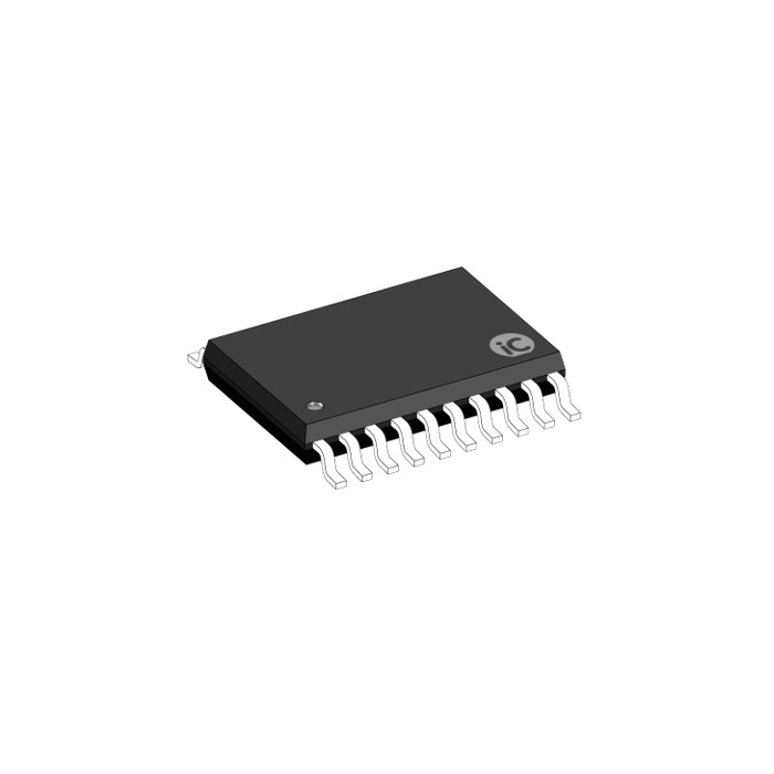
Megawin MG82F6D003AT20 TSSOP20
- 1-T 80C51 Central Processing Unit
- MG82F6D17 with 16K Bytes flash ROM
- ISP memory zone could be optioned as 0.5KB/1.0KB~7.5KB
- Flexible IAP size by software configured
- Code protection for flash memory access
- Flash write/erase cycle: 20,000 times
- Flash data retention: 100 years at 25℃
- Data RAM : 1K Bytes
- Onchip 256 bytes scratch-pad RAM
 768 bytes expanded RAM (XRAM)
- Support page select on XRAM access
₹75.00
Buy NowYour custom content goes here. You can add the content for individual product


Reviews
There are no reviews yet.