


In the world of photography, lighting plays a crucial role in capturing stunning images. While natural light is often preferred, there are situations where photographers need to rely on artificial lighting to achieve their desired effects. One such versatile lighting solution is RGB light, which allows photographers to experiment with a wide range of colours and create captivating visual compositions. An RGB light source is very much needed for product photography. In this article, we will explore how to build an RGB light using an ESP8266 microcontroller and NeoPixel LEDs, offering an affordable and customizable option for enhancing your photography. It has three inbuilt buttons to control the brightness and change the colour. Now let’s get started.

TESTING THE CIRCUIT
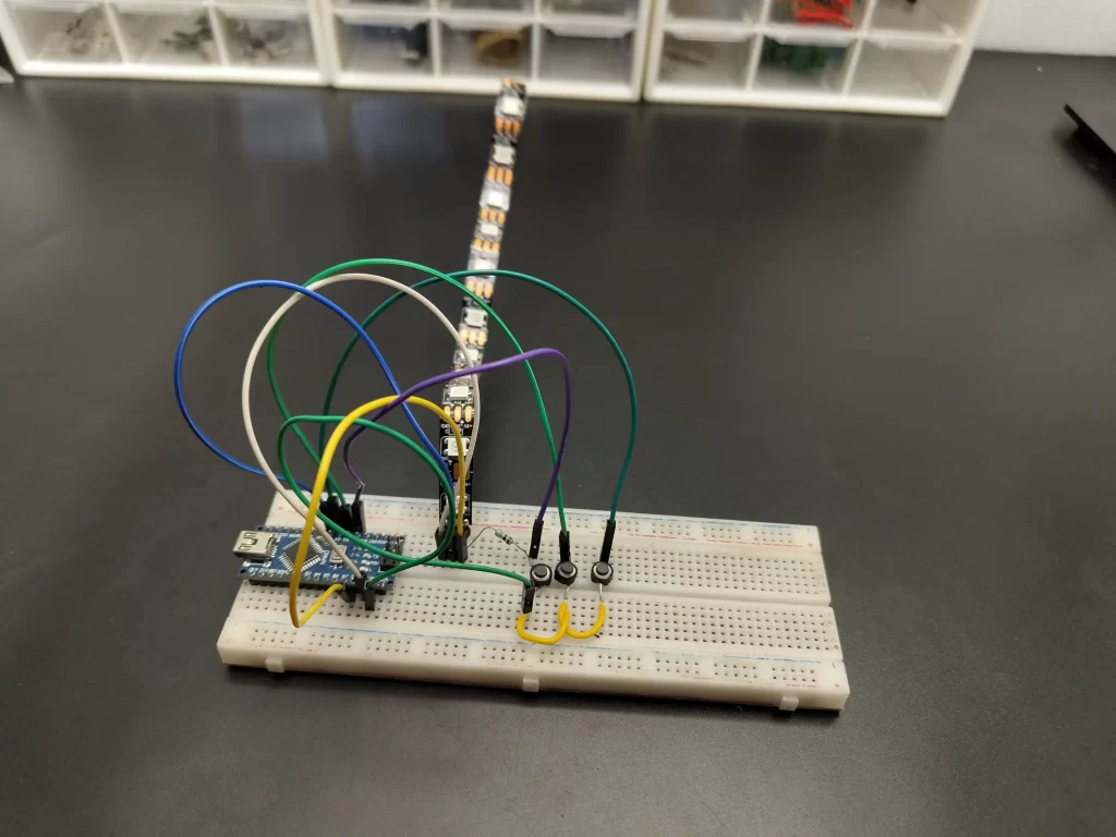
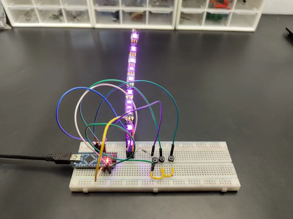
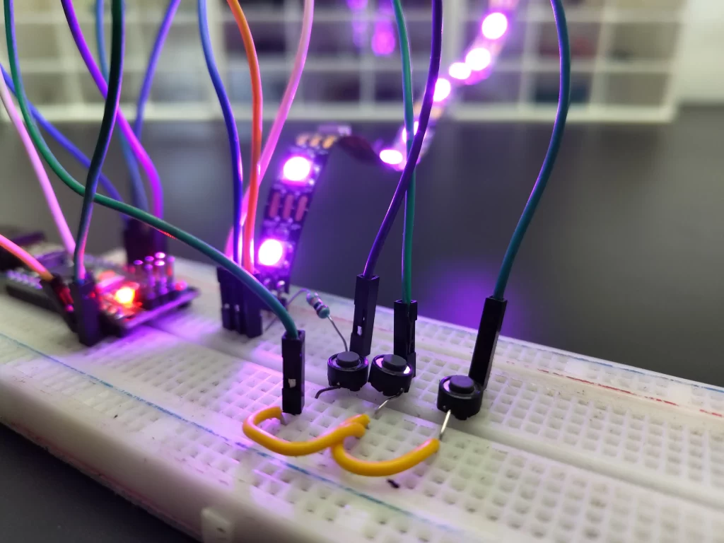
before going to build a circuit permanently it’s good to check and verify the circuit in the breadboard. Here I used an Arduino and ws2812 led strip to test the circuit. I used three push buttons to control the brightness and select the colour. after verifying the circuit and code I decided to build the circuit permanently note that I am going to use esp12e over Arduino nano.
COMPONENTS NEEDED FOR MAKING
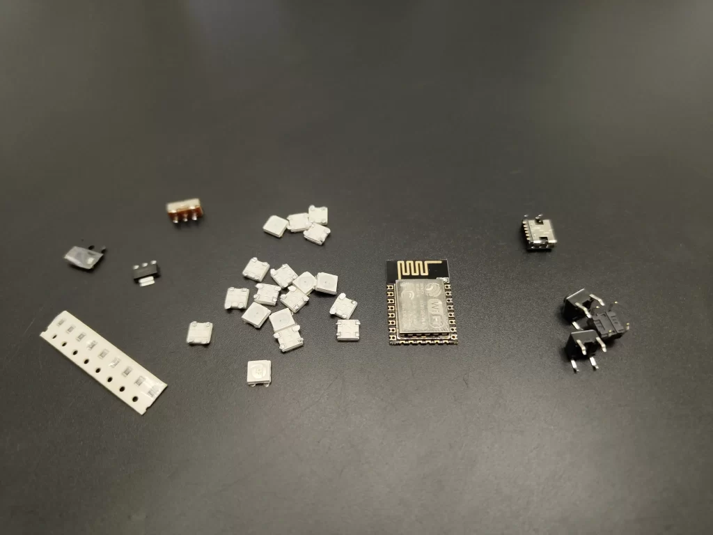
- ESP8266 microcontroller(ESP12E) -1 Nos
- WS2812B NeoPixel LEDs -16 Nos
- Push Buttons -3 Nos
- 3.7V Li-ion battery-1 Nos
- TP4056 charging module – 1 Nos
- 3.7 to 5v booster module -1 Nos
- AMS1117 3.3v regulator -1 Nos
- On/off Switch- 1 Nos
- 10K 0805 resistors -8 Nos
- 1K 0805 resistor -1 Nos
- 100nf 0805 capacitor -1Nos
CIRCUIT DIAGRAM
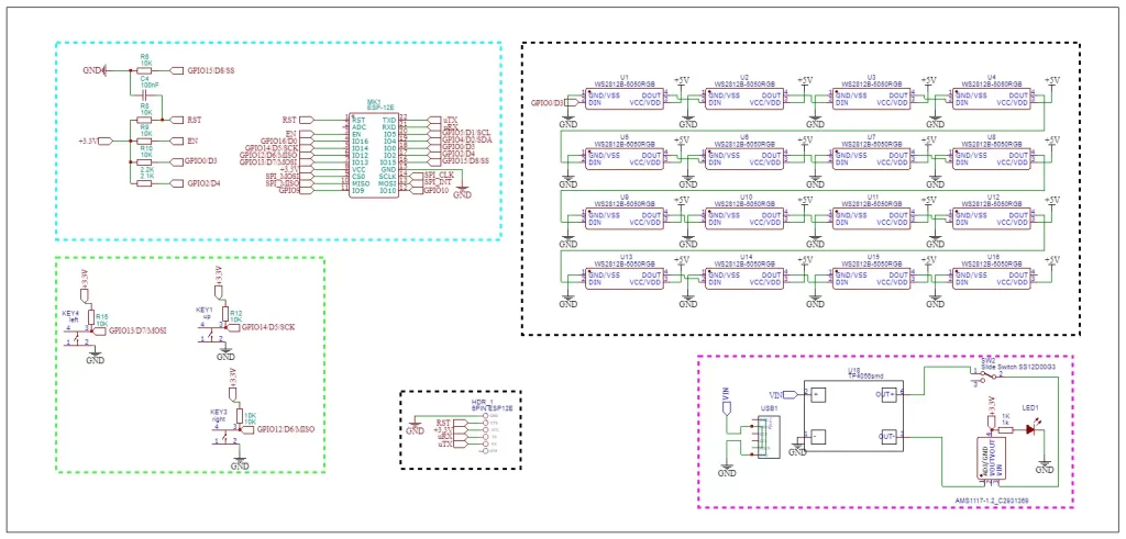
here is the circuit for this project the main component of this project is the esp12e or esp8266, we can programme this microcontroller easily using Arduino ide. Since I am using this module alone I have added the necessary components for the proper working of the esp12e.
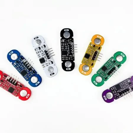
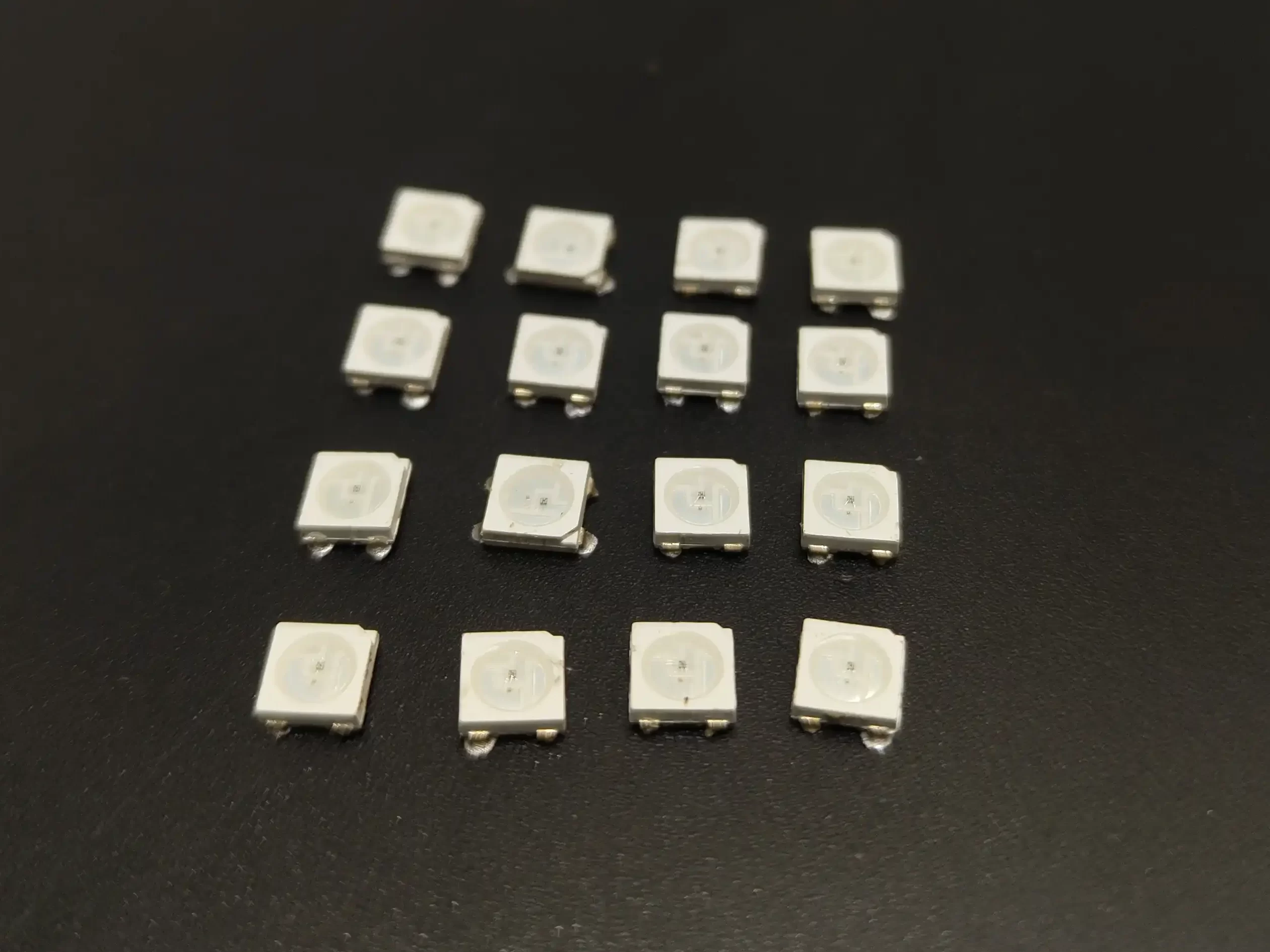
I used 16 ws2812b neopixel LEDs as a light source. The WS2812B is a popular addressable RGB LED (light-emitting diode) chip. It combines red, green, and blue (RGB) colour channels in a single package, allowing for individual control of each LED.
Here are some key features and characteristics of the WS2812B:
- Integration: The WS2812B integrates a red, green, and blue LED with a driver chip into a single package. This integration simplifies the wiring and control of individual LEDs.
- Addressable: Each WS2812B LED has a unique address, allowing for independent control of each LED in a chain or matrix of LEDs. This enables the creation of dynamic lighting effects and patterns.
- Data Transmission: The WS2812B uses a one-wire communication protocol to transmit data and control signals. The colour and brightness information for each LED is sent sequentially through the data line.
- Power Supply: The WS2812B requires a 5V power supply. It is essential to provide sufficient power to the LEDs to ensure proper functioning and prevent voltage drops.
- Compatibility: The WS2812B is compatible with various microcontrollers, development boards, and platforms. There are libraries and code examples available for popular platforms like Arduino, Raspberry Pi, and other microcontroller-based systems.
- Cascading: WS2812B LEDs can be cascaded together to create longer LED strips or larger matrices. Each LED receives and processes the data signal before passing it on to the next LED, allowing for easy scalability.
- Programming: To control WS2812B LEDs, you must write code that sends the appropriate data signals to the LEDs. This involves specifying the colour and brightness values for each LED in the chain or matrix.
- Libraries and Resources: Various libraries and resources are available that simplify the programming of WS2812B LEDs. These libraries provide functions to control the LEDs and create different lighting effects without having to handle low-level data transmission.
To make this project portable I used a 3.7v li-ion battery. so to charge this battery I added a tp4066 charging module. That’s basically all about the circuit. since the WS2812 LEDs are SMD package I have decided to build a compact PCB.
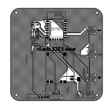
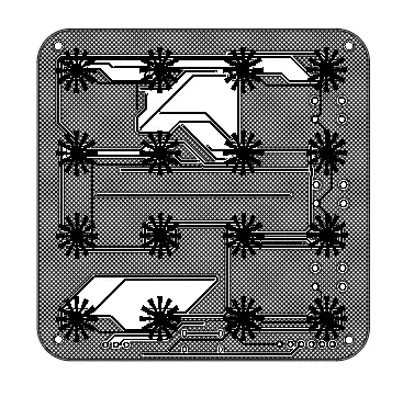
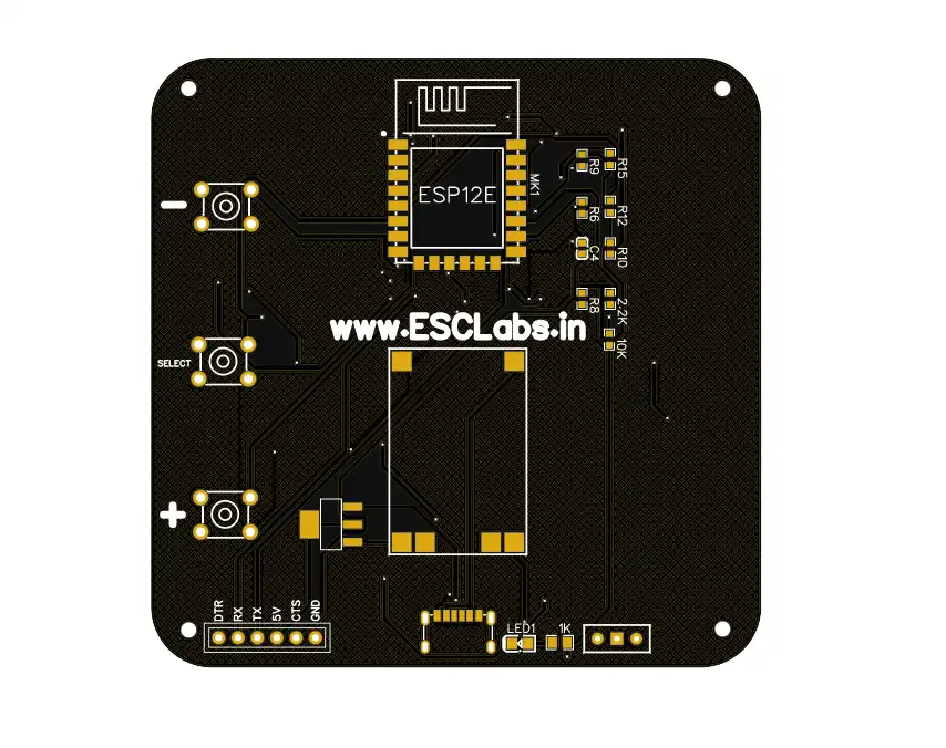
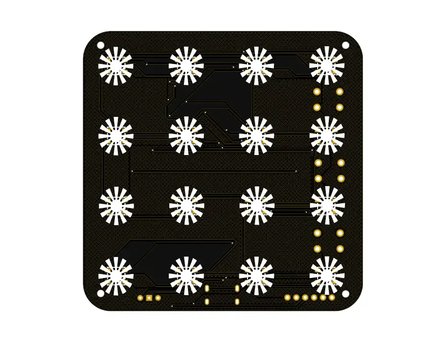
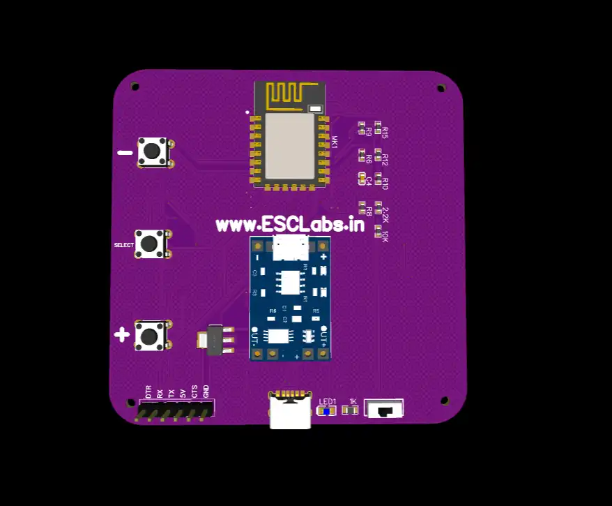

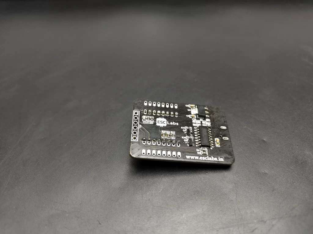
I used easyeda.com to make the PCB. I placed Neopixel led on the top side of the PCB and all components on the bottom side. after making the PCB I downloaded the Gerber files for PCB fabrication.
you can download the Gerber file from here
PCB fabrication
JLCPCB is a professional PCB (Printed Circuit Board) manufacturing company based in China. They specialize in providing high-quality PCB fabrication and assembly services to customers worldwide. I chose jlcpcb because they offer 5 PCBs just for 2$ and their PCB assembly starts from zero dollars.
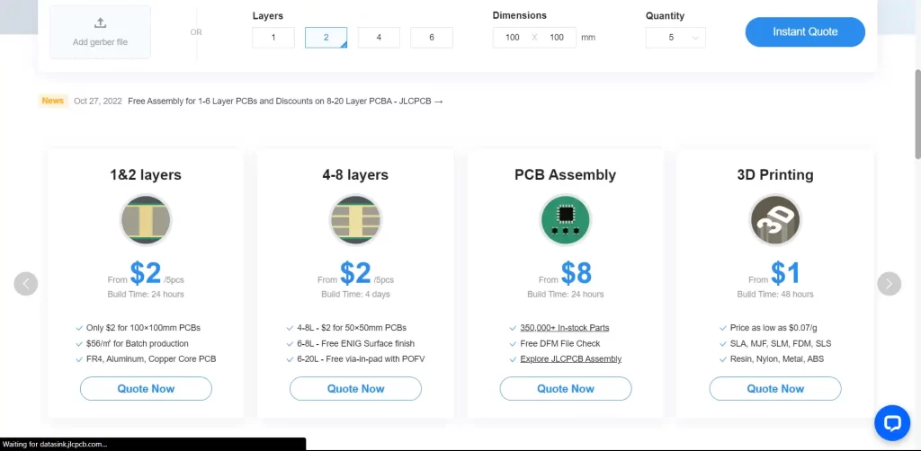
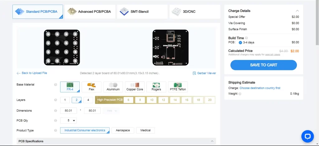
Ordering PCBs from jlcpcb is very easy first go to jlcpcb.com and log in with your account then click on order now then just upload the PCB Gerber file. now if you want you can customize the PCB settings like thickness, colour, quantity etc. Finally, select the shipping method and pay the bill, that’s it.


here are the received PCBs from jlcpcb. As always I got the high-quality professional PCBs from jlcpcb
SOLDERING COMPONENTS IN PCB
The next step is grabbing the soldering iron and components. this is a simple process just place the components on PCB according to the PCB and solder that’s it

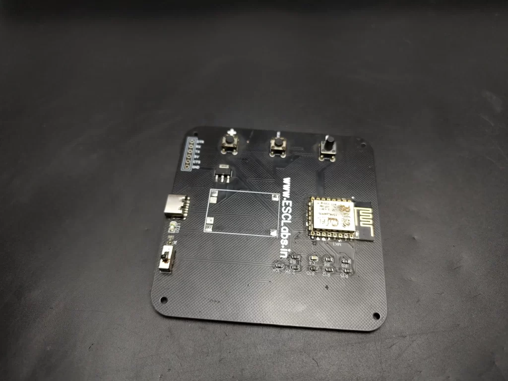
here are the finished PCBs. I cleaned the PCBs after soldering all components. Here you can see I haven’t added the TP 4056 modules that’s because now I am planning to power this through USB. So that’s basically all about the electronics setup, now it’s time to upload the code to esp12e.
ARDUINO CODE
This Arduino code is designed to control a strip of WS2812 LEDs (also known as NeoPixels) using a button and two push buttons for increasing and decreasing brightness. I’ll explain the code step by step.
#include <FastLED.h>
#define DATA_PIN 0
#define NUM_LEDS 16
#define LED_TYPE WS2812
#define COLOR_ORDER RGB
int pin = D6;
int p = 0;
int buttonState = 0;
int lastButtonState = 0;
CRGB leds[NUM_LEDS];
const int Up_buttonPin = D5;  // the pin that the pushbutton is attached to
const int Down_buttonPin = D7;
int buttonPushCounter = 0;  // counter for the number of button presses
float up_buttonState = 0;  // current state of the up button
float up_lastButtonState = 0;  // previous state of the up button
float down_buttonState = 0;  // current state of the up button
float down_lastButtonState = 0;  // previous state of the up button
bool bPress = false;
#define UPDATES_PER_SECOND 100
first I have added the fastled library which is used to control the WS2812 LEDs efficiently.
then I defined various constants related to the LED strip, such as the data pin, the number of LEDs in the strip, LED type (WS2812), colour order (RGB) etc. For example, pin represents a button’s pin, p is used to store the LED pattern, and LEDs are an array to store LED colours.
void setup() {
  Serial.begin(9600);

  pinMode(Up_buttonPin, INPUT_PULLUP);
  pinMode(Down_buttonPin, INPUT_PULLUP);
  pinMode(pin, INPUT_PULLUP);

  FastLED.addLeds<NEOPIXEL, DATA_PIN>(leds, NUM_LEDS);

  if (p < 0 || p > 8) {
    p = 0;
    delay(10);
  }
}
The setup function is executed once when the Arduino starts. It initializes the serial communication, sets pin modes, and adds the LED strip.
void loop()

{
  if (digitalRead(pin) == LOW) {
    buttonread();
  }
  Serial.print("pin: ");
  Serial.println(digitalRead(pin));

  FastLED.setBrightness(buttonPushCounter);
  checkUp();
  checkDown();

  if (bPress) {

    bPress = false;
  }

  if (p == 1)  //both on
  {
    for (int i = 0; i < 16; i++) {
      leds[i] = CRGB::Red;
      FastLED.show();
      delay(50);
    }
  }
  if (p == 2) {
    for (int i = 0; i < 16; i++) {
      leds[i] = CRGB::Green;
      FastLED.show();
      delay(50);
    }
  }

  if (p == 3) {
    for (int i = 0; i < 16; i++) {
      leds[i] = CRGB::Blue;
      FastLED.show();
      delay(50);
    }
  }
  if (p == 4) {
    for (int i = 0; i < 16; i++) {
      leds[i] = CRGB::Magenta;
      FastLED.show();
      delay(50);
    }
  }
  if (p == 5) {
    for (int i = 0; i < 16; i++) {
      leds[i] = CRGB::Cyan;
      FastLED.show();
      delay(50);
    }
  }

  if (p == 6) {
    for (int i = 0; i < 16; i++) {
      leds[i] = CRGB::White;
      FastLED.show();
      delay(50);
    }
  }

  if (p == 7) {
    for (int i = 0; i < 16; i++) {
      leds[i] = CRGB::White;
      FastLED.show();
      delay(50);
    }
  }
  if (p == 8) {
    p = 0;
  }

  Serial.println(p);
  delay(1);
  Serial.print(buttonPushCounter);
}
in the loop section first checks if the button connected to the pin is pressed. If the button is pressed (LOW), it calls the buttonread() function. This function is likely used to change the value of p. With the help of if conditions I have defined each colour for each p-value. for example if p=1 then red will light up.
you can download the complete code from here
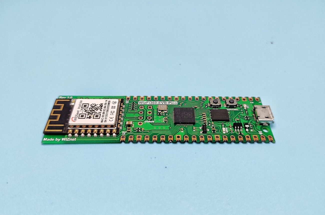
UPLOADING CODE TO ESP12E

I used this esp programmer for uploading the code.
ENCLOSURE MAKING
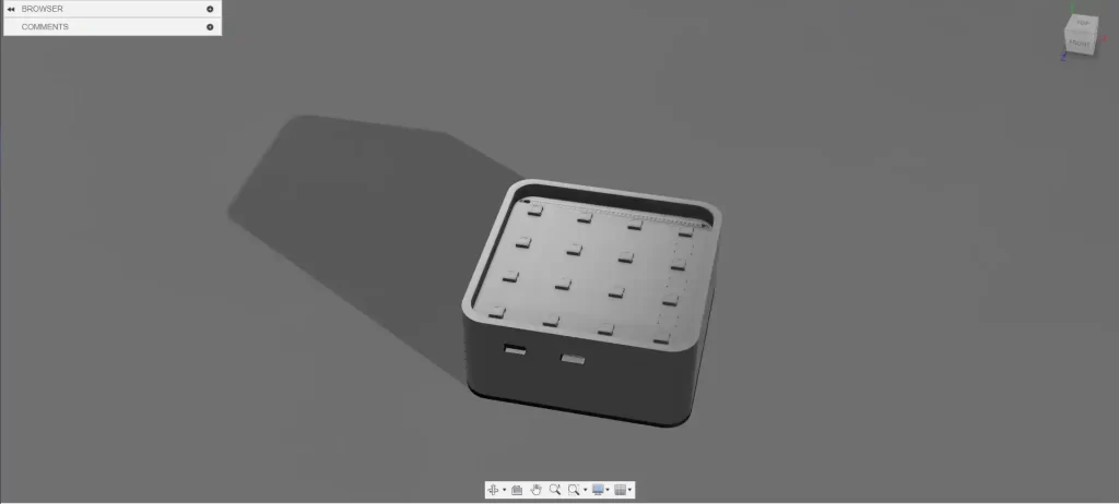

It’s better to enclose everything together in a box, Using Fusion 360 I made this design. This design has three parts a front panel for diffusing the light, the main body and the back frame.


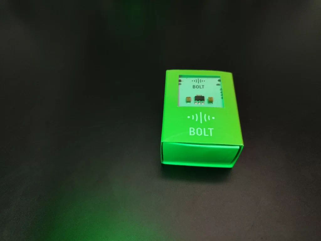
using my Ender 3 I have printed the parts and assembled it together
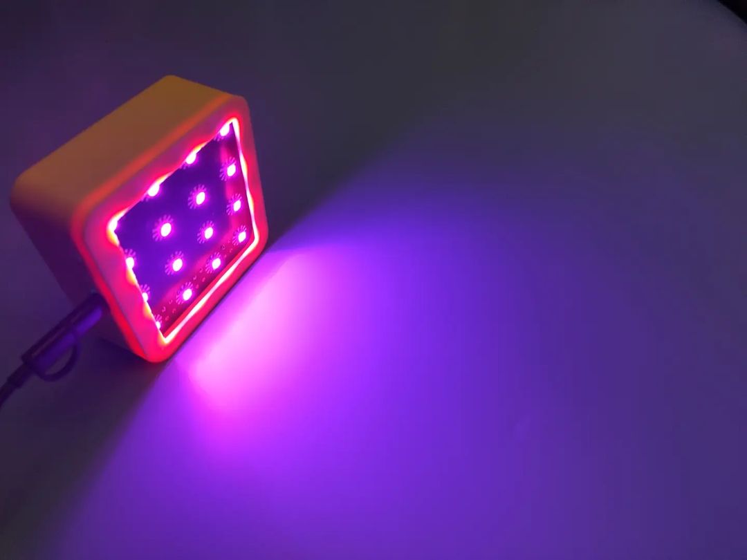
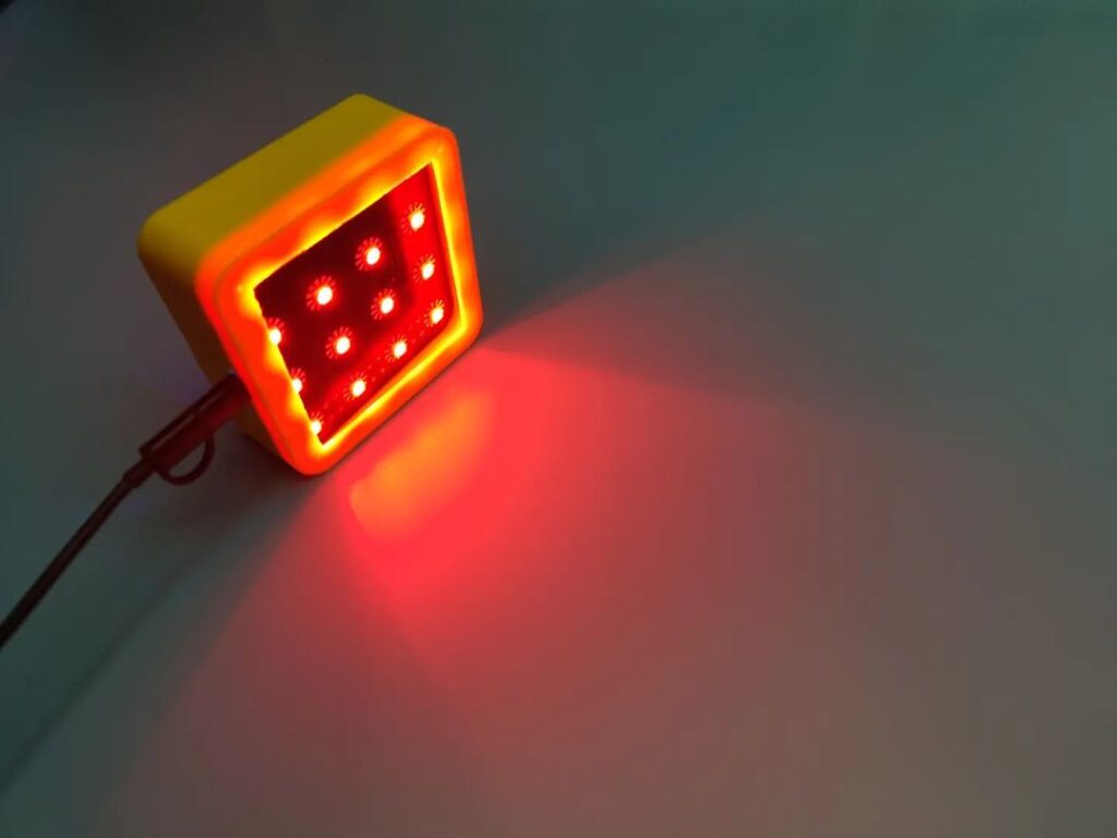
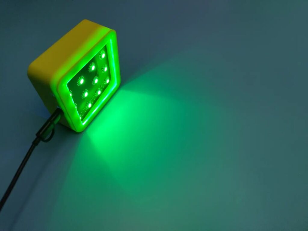
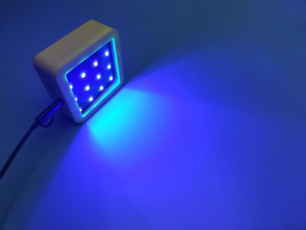
RESULT


Here you can see the clear difference between the images. the image quality and looks great while using the RGB light.
VIDEO TUTORIAL


Leave a comment