


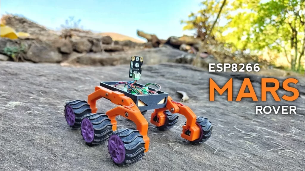
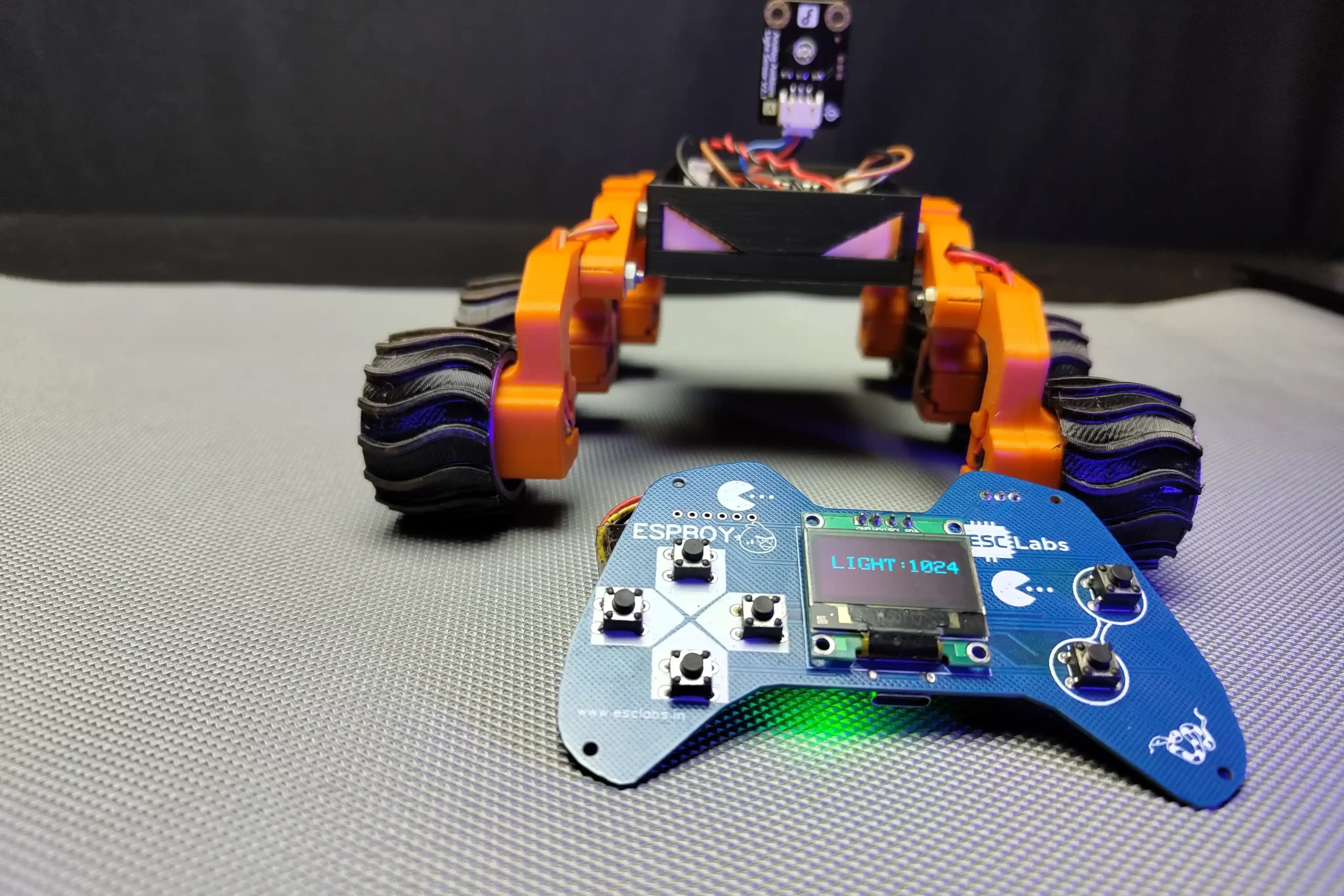
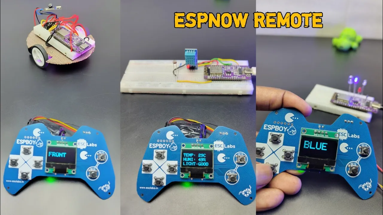
A Mars rover is a remote-controlled robot designed to travel on the surface of Mars. we have seen several Mars rovers like Spirit, Opportunity, Curiosity and Perseverance. these rovers are highly designed to operate on uneven terrains. Have you ever wondered how rovers navigate the rough terrain of Mars? Their secret weapon is the ingenious rocker-bogie suspension system. I was amazed with the 6-wheel rocker-bogie system. Because of this interest, I have made a 6-wheel rocker bogie model Mars rover. The major part of this simple model is 3D printed, this rover can be controlled by a dedicated remote controller or we can use a smartphone application. We can read the data of the attached sensors (any sensors) and we can see the data through the remote controller OLED screen. The rover uses ESP12E as the brain and L293D as the motor controller. The remote controller uses the same ESP12E microcontroller. the communication between the rover and the remote is using the ESPNOW protocol. So This project is perfect for anyone interested in space exploration, robotics, or 3D printing. Now let’s see how you can build your own.
ESPNOW Communication
ESP-NOW is a communication protocol developed by Espressif Systems, the company behind the ESP8266 and ESP32 series of microcontrollers. It’s designed for low-power, peer-to-peer communication between ESP8266 and ESP32 devices, enabling efficient data exchange without the need for a traditional Wi-Fi network or internet connection. ESP-NOW provides basic security features such as message encryption to protect the transmitted data from unauthorized access. However, it’s important to note that it may not offer the same level of security as more robust protocols like WPA2 used in traditional Wi-Fi networks. In simple words, we can transmit and receive data from one ESP board to another without using any external components. By using espnow we can decrease the total cost of the project.
COMPONENTS NEEDED
Here I am using mostly SMD components for building the rover and remote. you can use the same to you can use THT components(same value) if you want to build the rover without PCB.
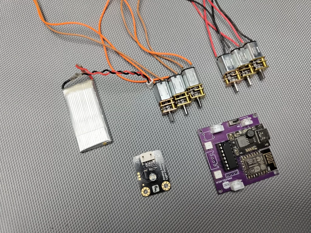
- NodeMCU -2 Nos
- L293D motor driver-1 Nos
- N20 gear motors(60-100rpm)-6 Nos
- 3.7v li-ion Battery – 1 Nos
- 3.7v to 5v Booster – 1 Nos
- ESP12E -1 (following components is for DIY PCB)
- 3.3V Regulator AMS1117-1
- 4-pin female JST connector -1
- 2-pin female JST connector -3
- 4-pin header -1
- WS2812B neopixel -2
- pushbutton-1
- 10k 0805 resistor-7
- 330 ohm 0805 resistor-2
- 8050 SMD transistor -2
- 100nf 0805 capacitors-6
- type C USB connector-1
CIRCUIT DIAGRAM
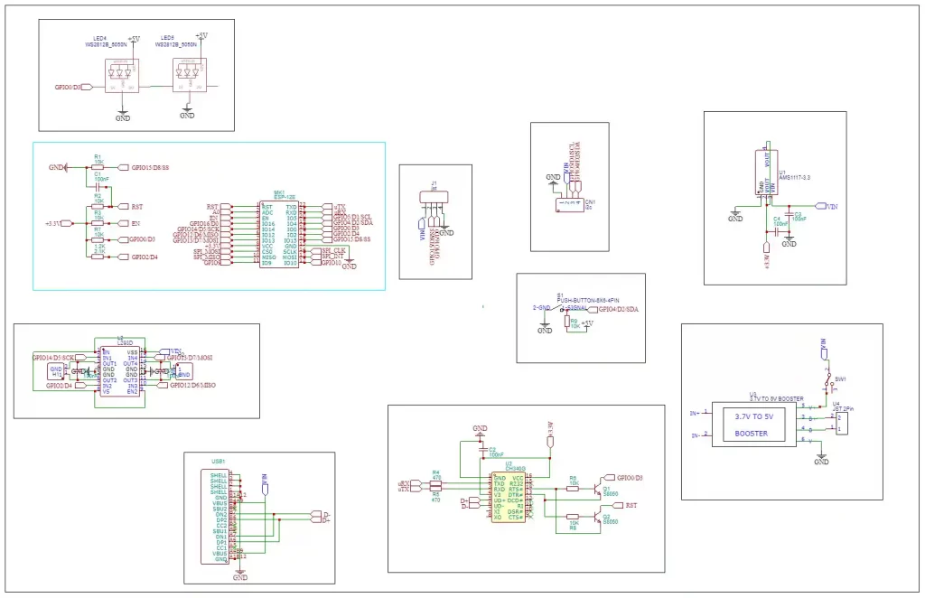
In this circuit diagram, I have used the esp12e microcontroller as the brain. it has enough pins to control the motor and it has one analogue pin to detect the sensor data. another main reason to choose this module is because it has wifi so we can control this module by wifi and espnow communication. To control the motors I used the L293D dual channel H bridge driver, with L293D we can control two motors bi-directionally at a time. also, I added two neopixels and a battery charging module to the circuit.
PCB DESIGNING
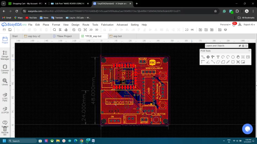
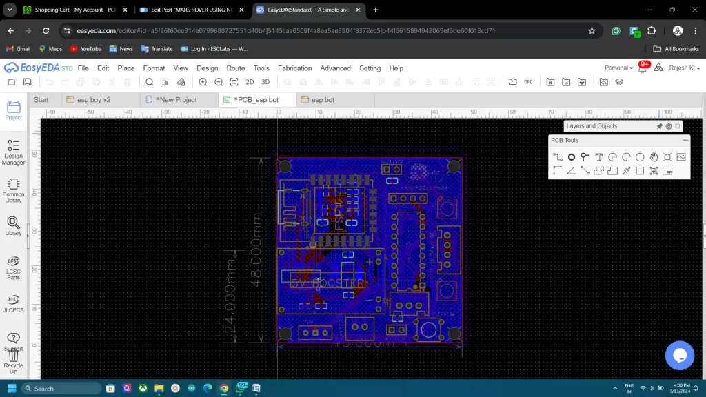
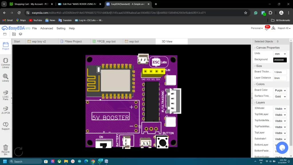
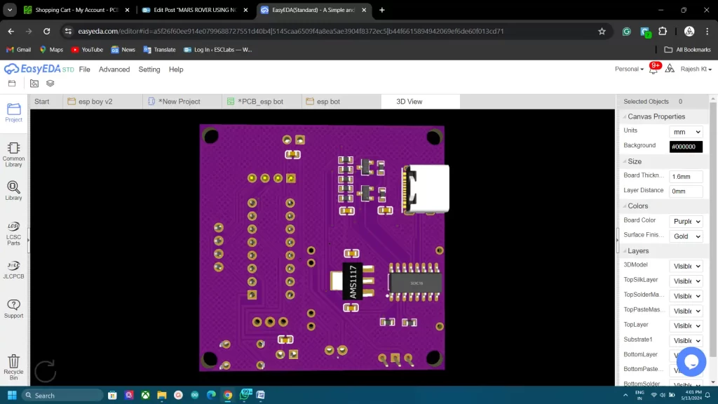
After testing and verifying the circuit using nodemcu on a breadboard, I decided to finalise the PCB design. So I converted the circuit diagram into a PCB. I arranged all the components closely and I finished the PCB design. The PCB looks something like this after designing. after varifing the PCB design once again I downloaded the Gerber files for PCB fabrication.
PCB FABRICATION
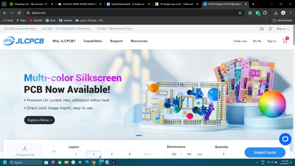
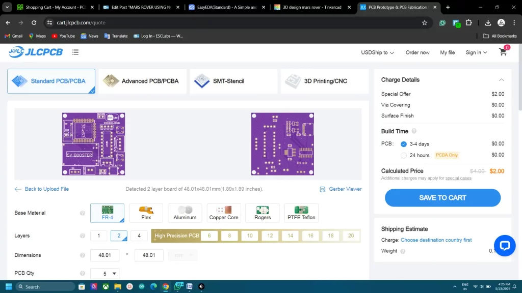
To fabricate the designed PCBs I went to jlcpcb.com. They are the best PCB manufacturers in China. You will get 5pcbs for just 2$ and their PCB assembly starts from 0$. now they also started high-quality Multicolour silkscreen printing. After logging in to your account, Click on Order now and upload the gerber file, after that, we can select colour, quantity, thickness etc. Here I choose purple colour for my PCBs. You can choose any colour. Then we can select the shipping method and we can place the order.
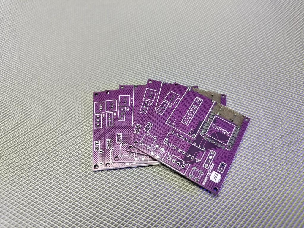
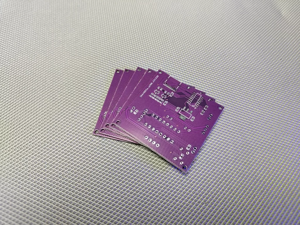
After two weeks I received the PCB from JLCPCB. The quality of the fabricated PCB is awesome. The purple makes the PCBs unique
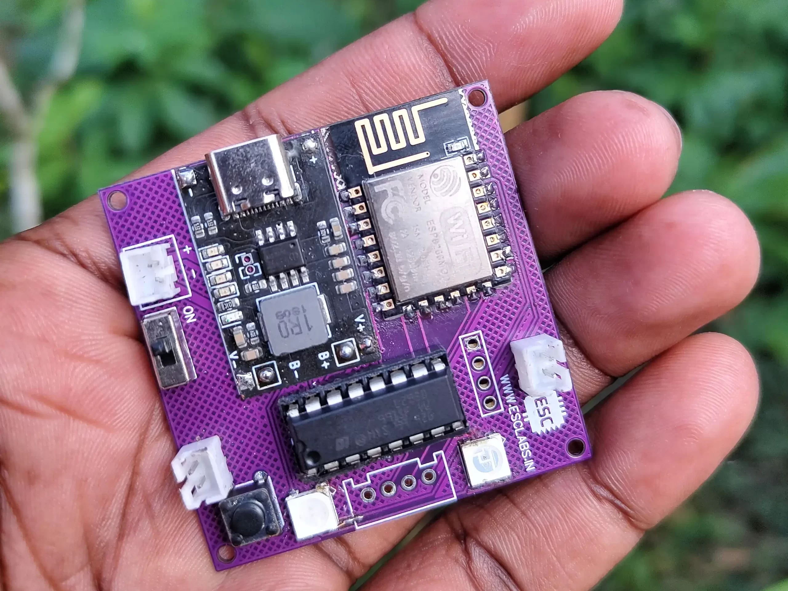
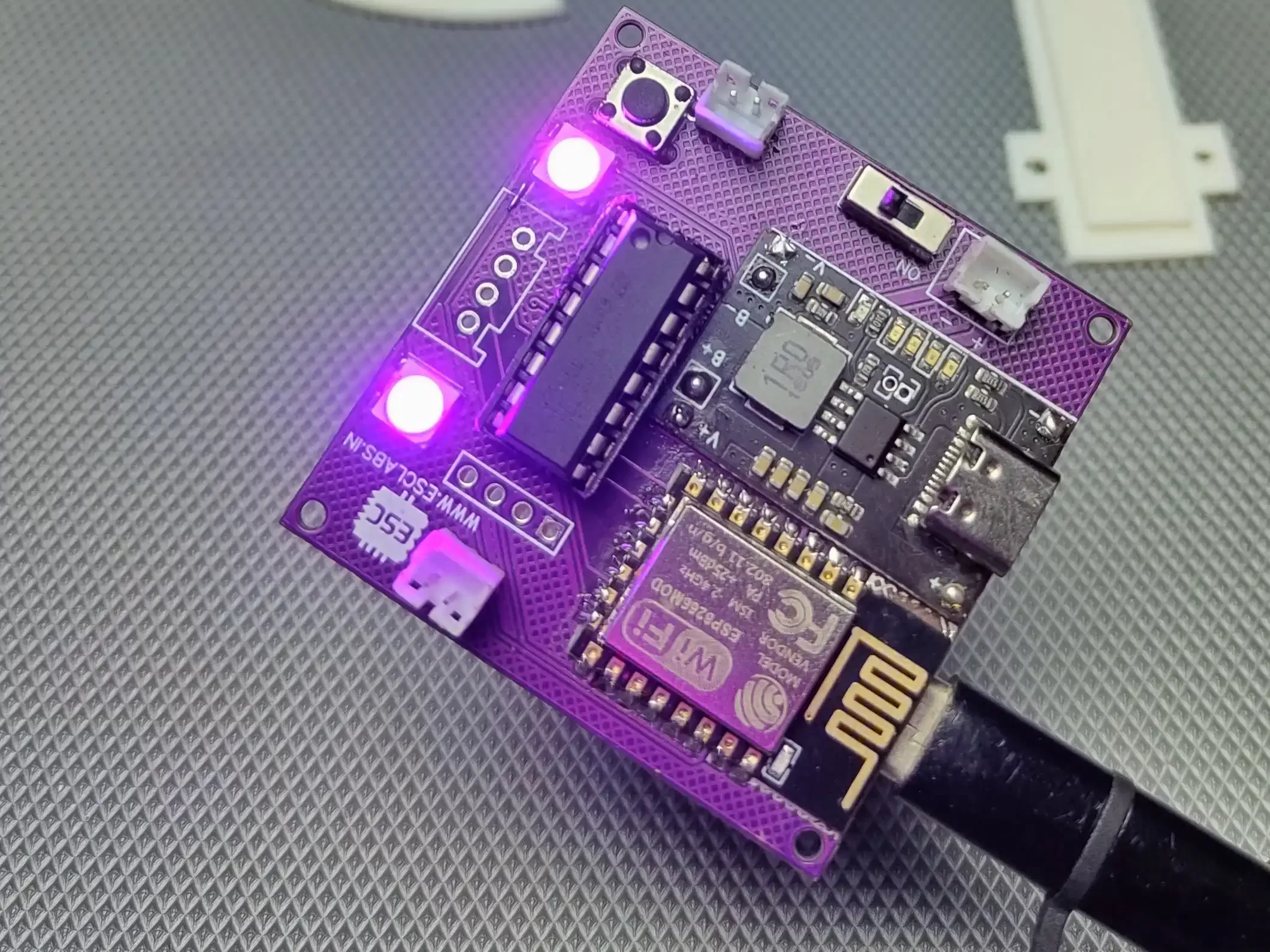
Now I grabbed all the components and started the soldering. I started with SMD components and then soldered the through-hole components. it’s very easy to solder the components on a designed PCB. I finished the soldering after 30 minutes. This is the finished PCB.
3D DESIGNING
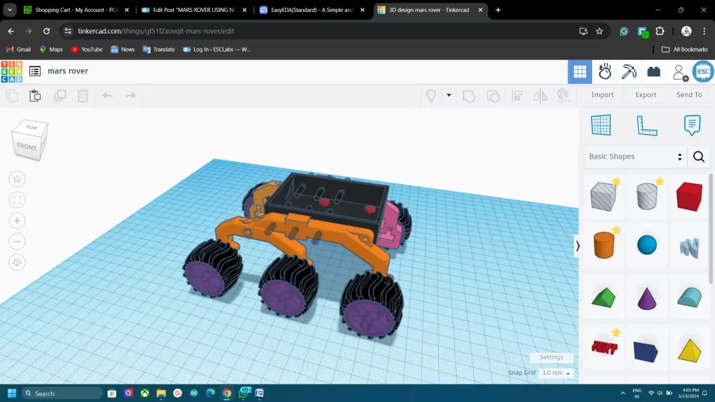
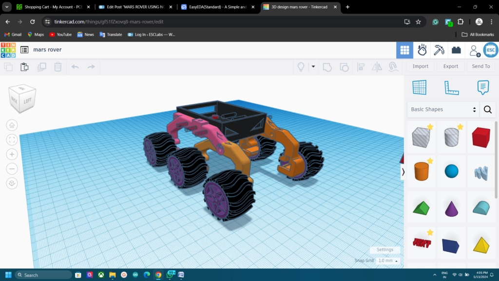
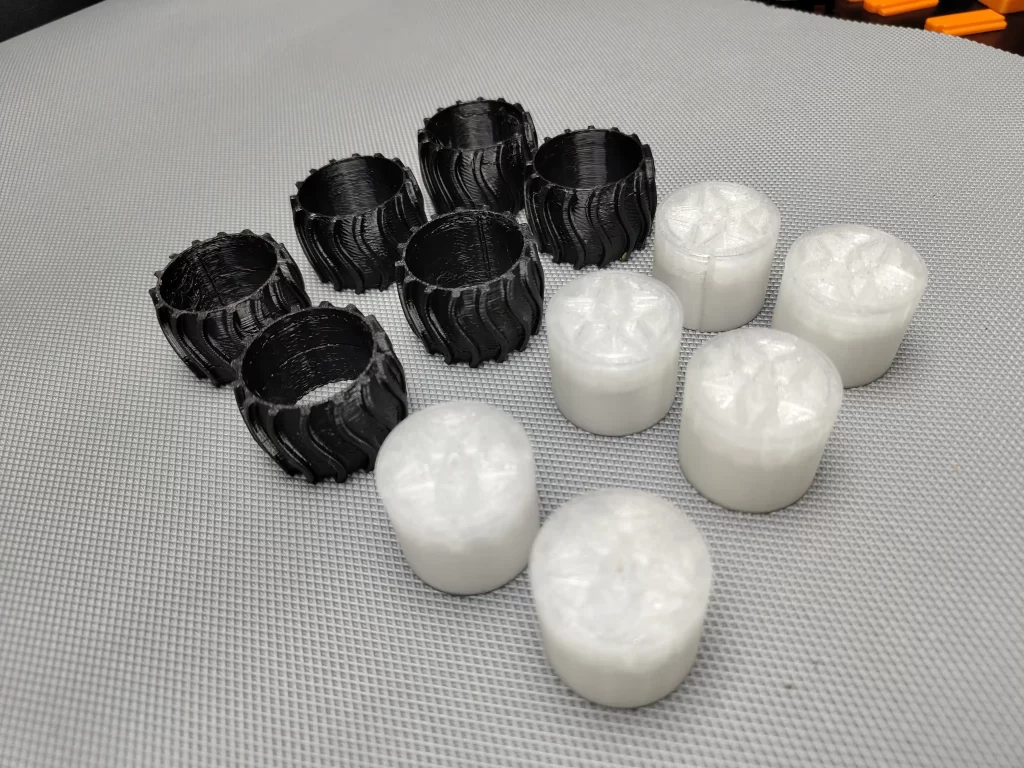
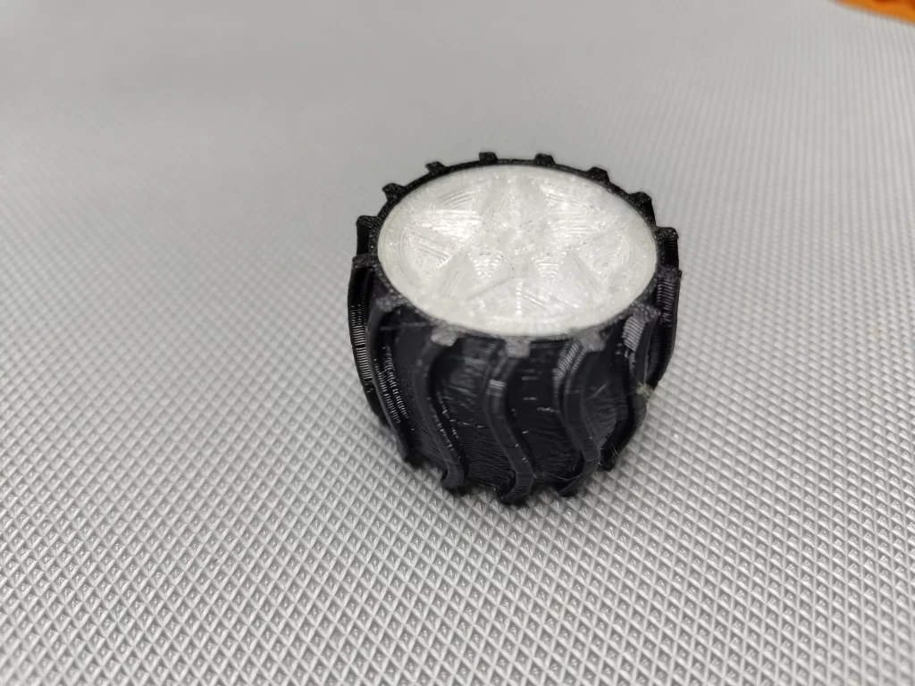
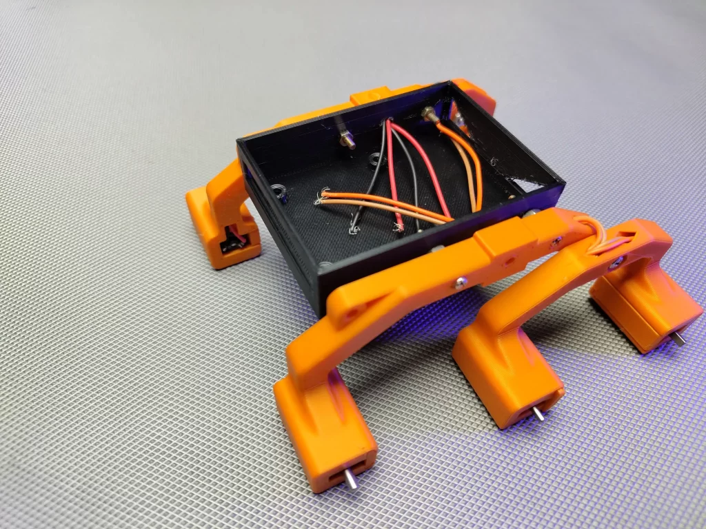
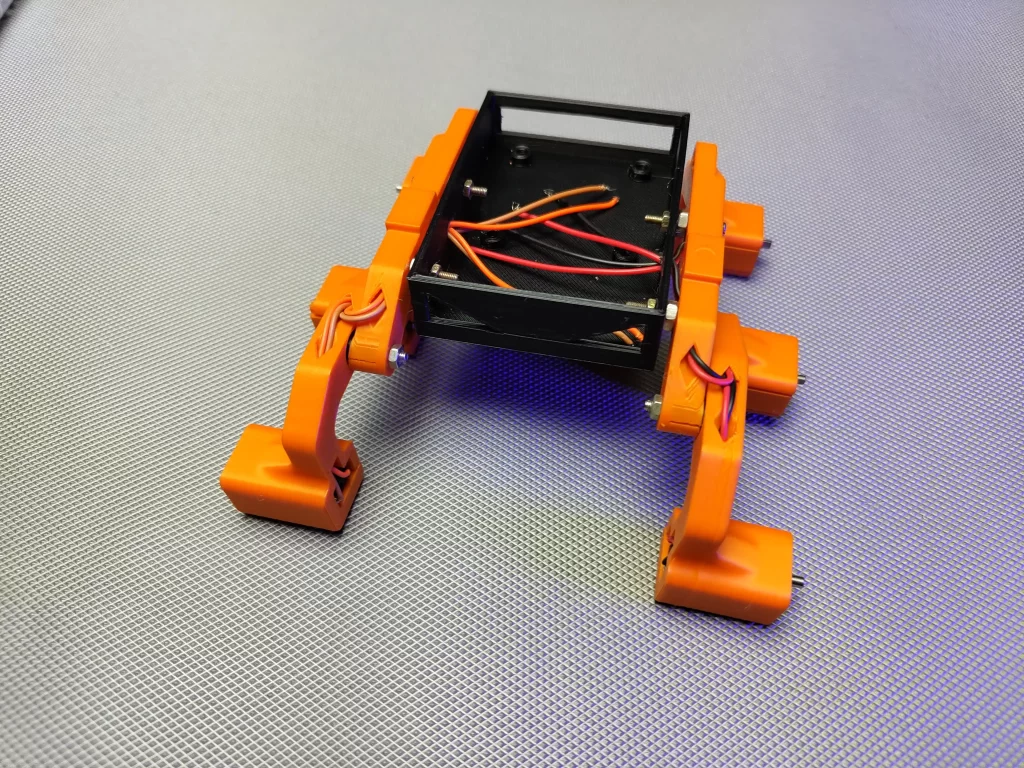
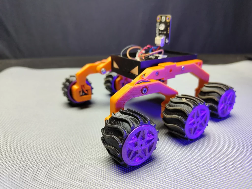
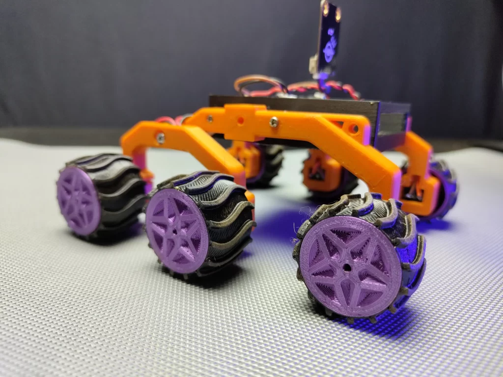
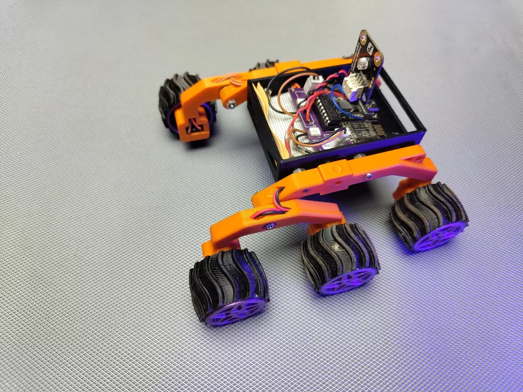
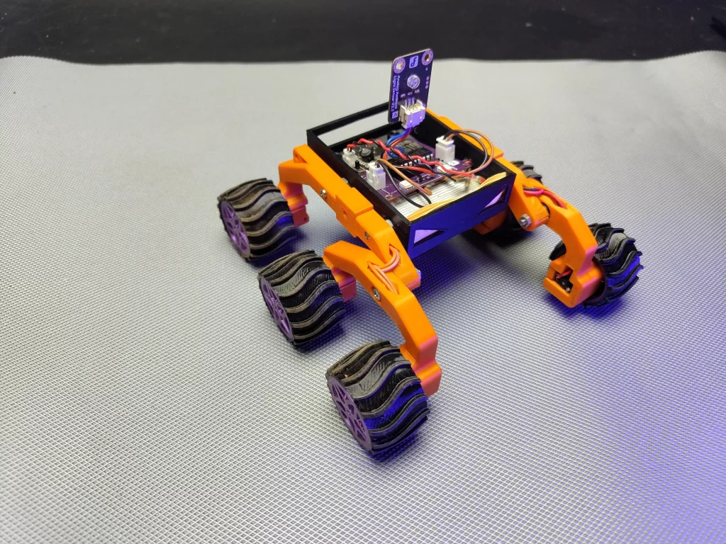
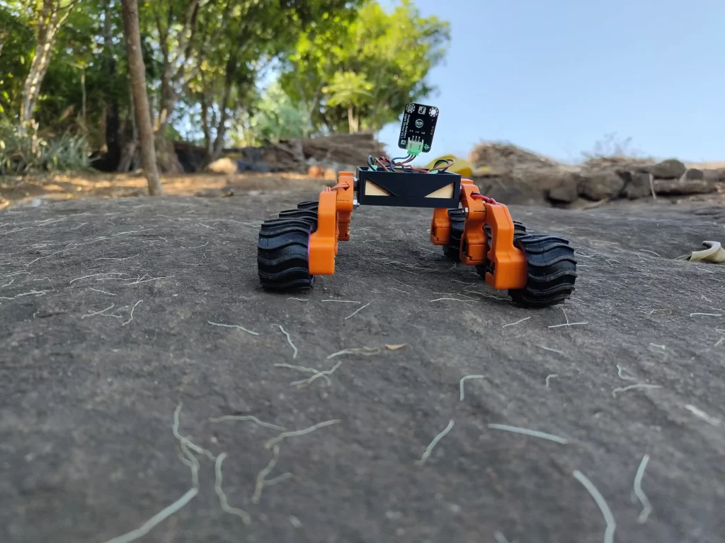
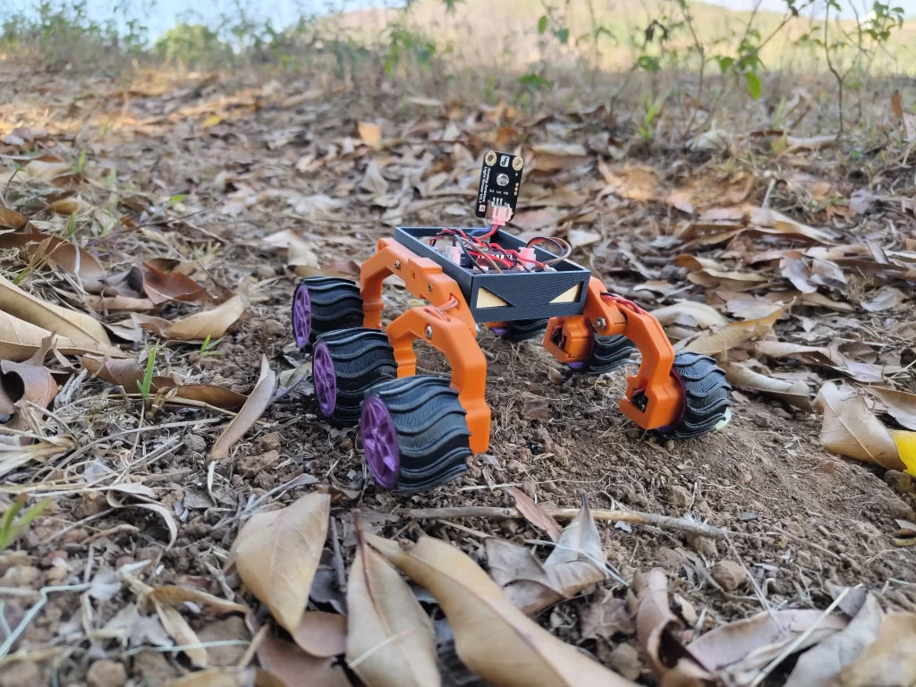
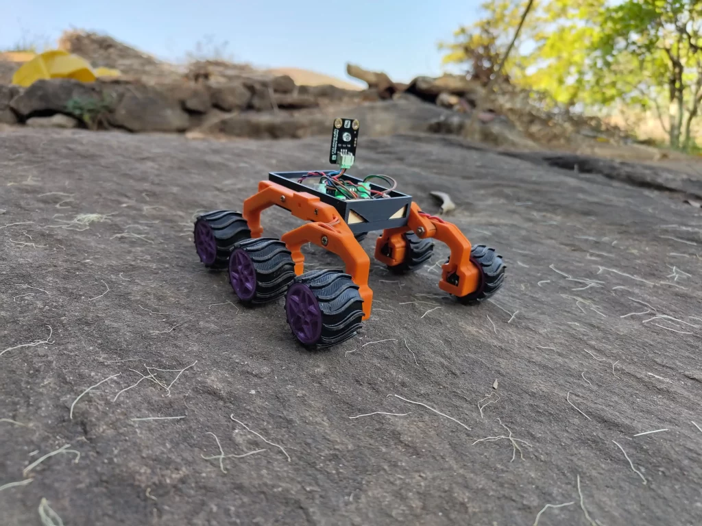
Now I need to build the body. For that First I downloaded some models from Thingiverse. And I modified it for my rover using tinkercad. The rover is a rocker-bogie mechanism-based bot. The main body of the rover is the black rectangular structure in the centre. I am planning to enclose all the electronic parts of the rover here, including the battery. The rocker-bogie mechanism used here is the same as the actual Mars rover mechanism, which allows the rover to traverse uneven terrain. The rover has six wheels with a distinctive tread pattern, designed for traction on the Martian surface.
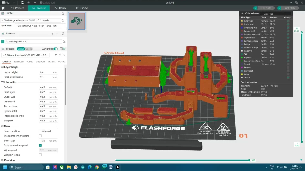
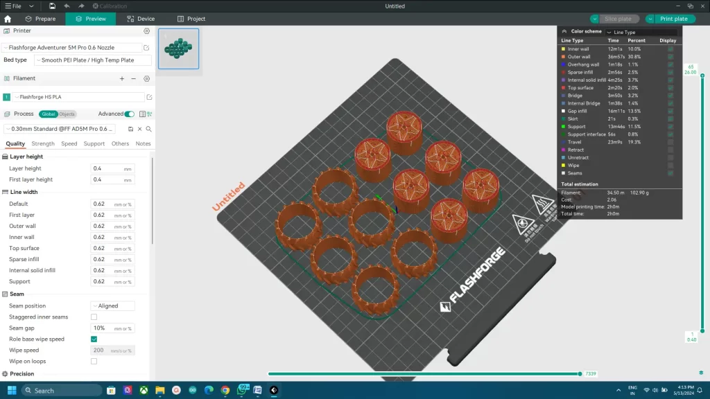
I used my flashforge adventurer 5m Pro for printing the models. I used PETG filament for the wheels and TPU for the tyres. Rest I printed with normal PLA. And my 5m pro is great for handling multiple materials. If you don’t have 3D printers you can order 3d printed parts from me. Check the description for that. download from here
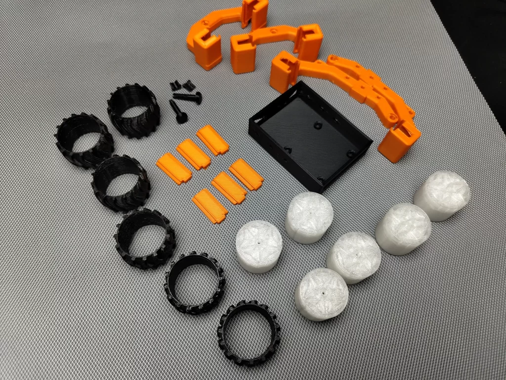
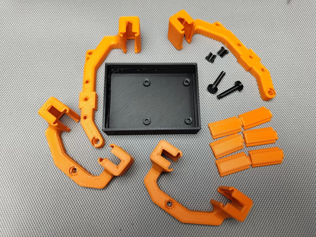
I used different coloured filaments for different parts. The main body I printed using black PLA filament. The other parts I printed using orange filament. I think the Orange-Black combo makes a different and good look.
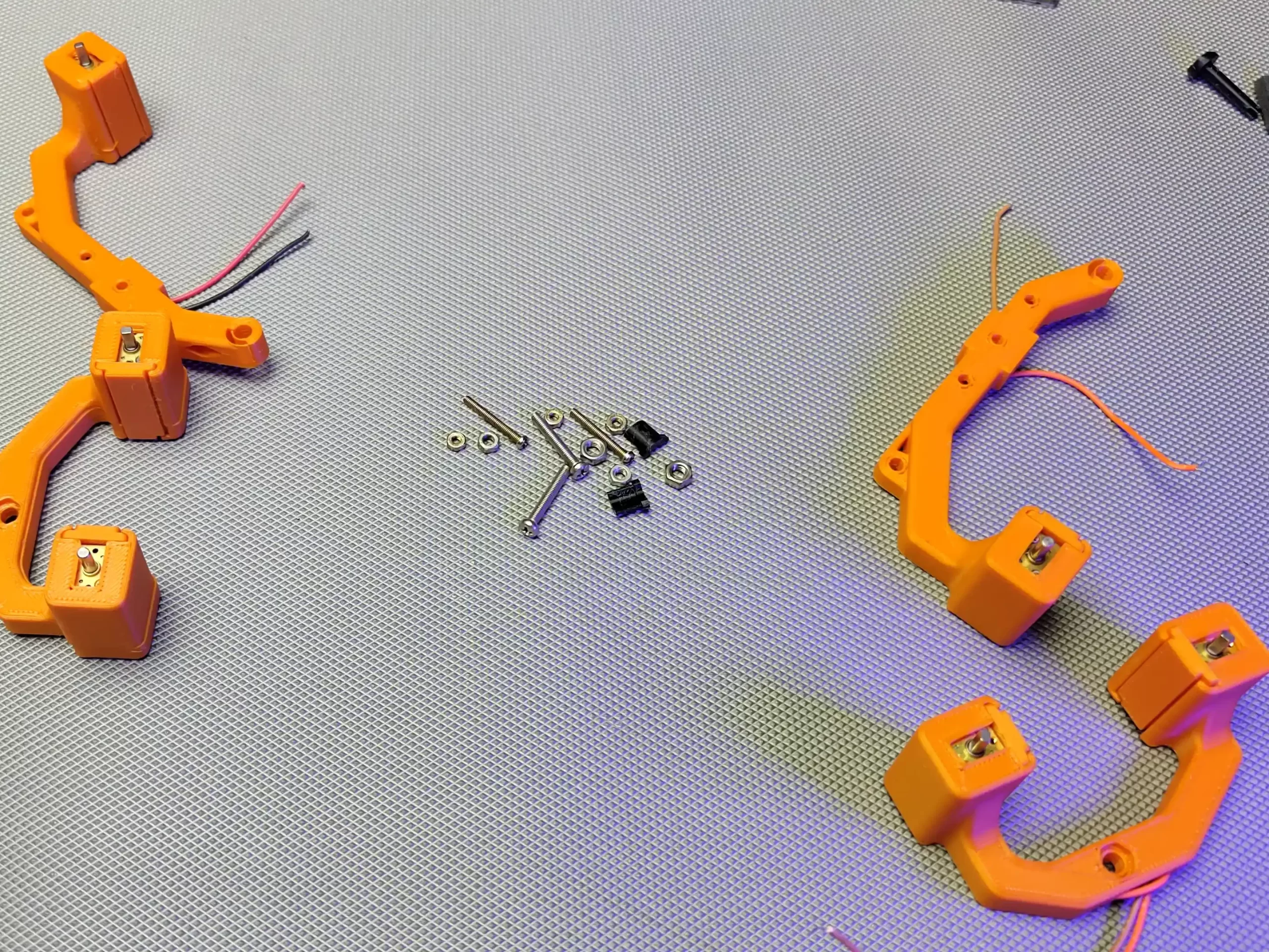
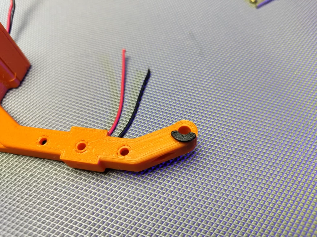
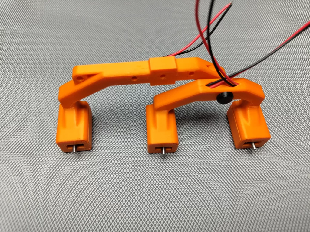
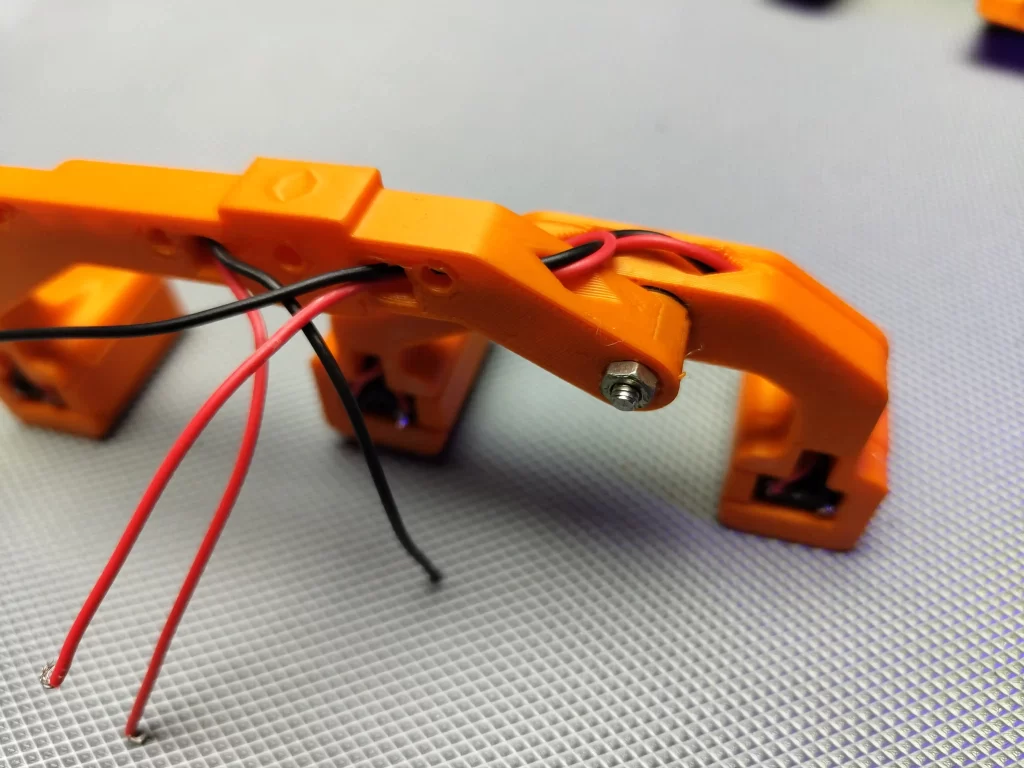
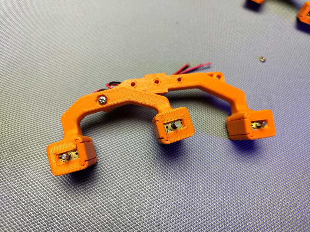
MARS ROVER BUILDING
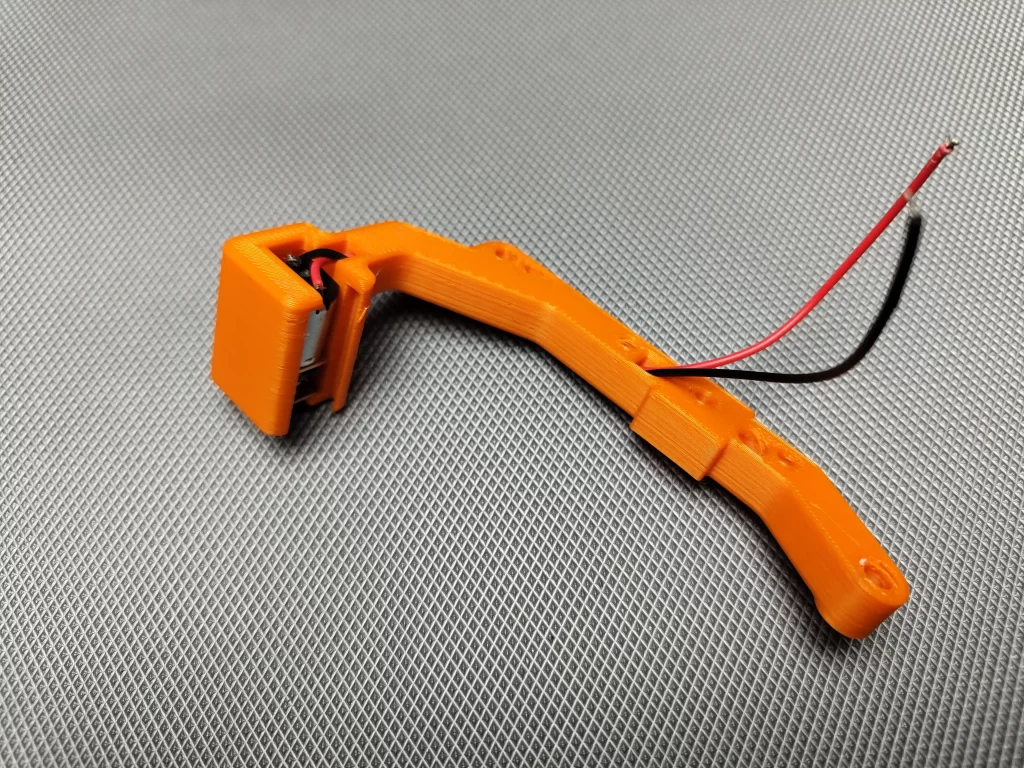
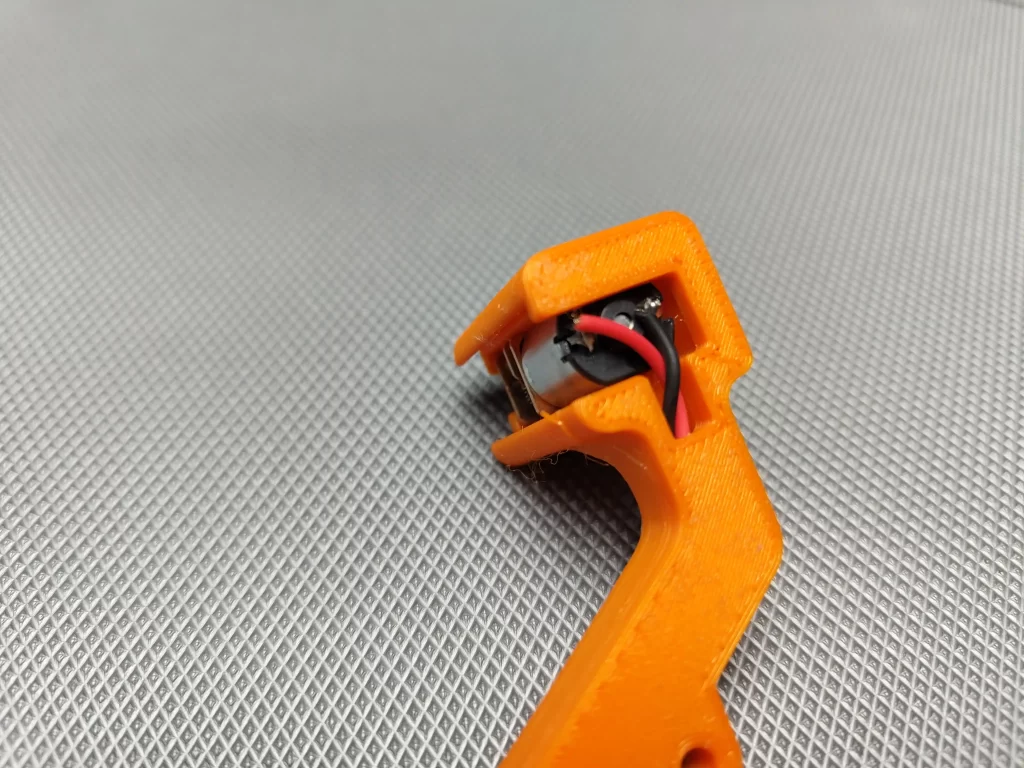
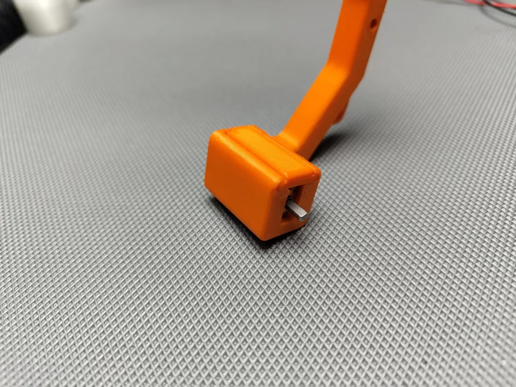
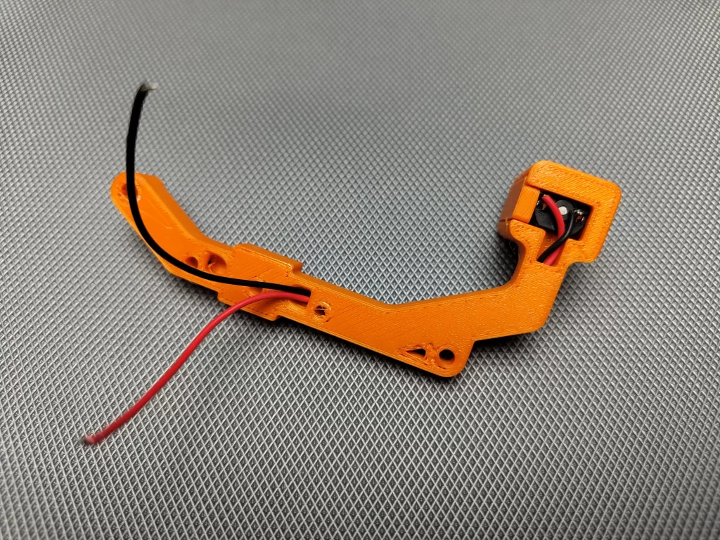
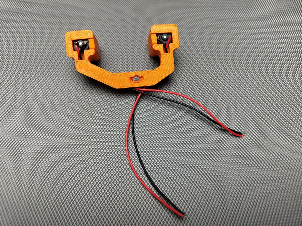
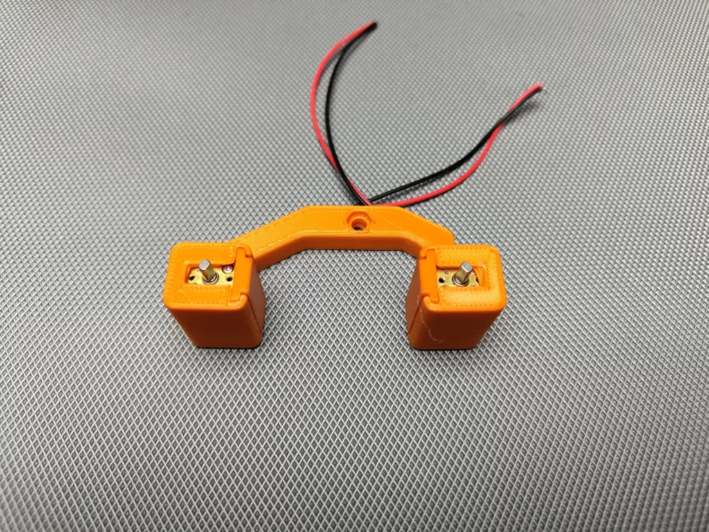
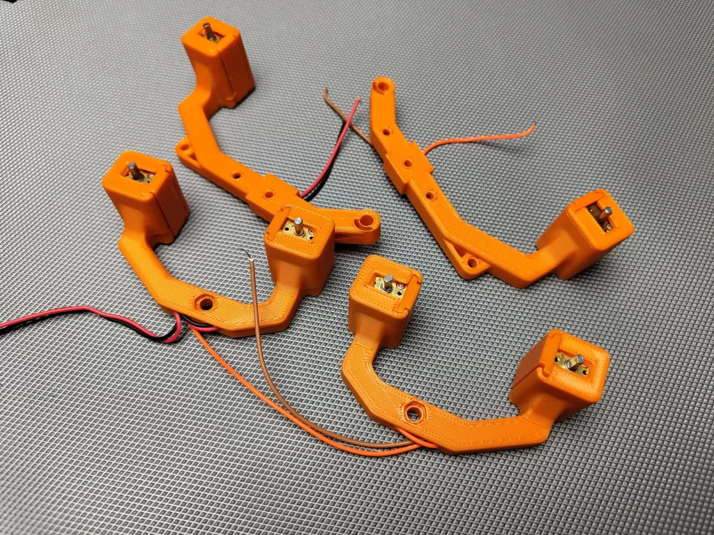
After printing the model first removed the support materials, then I cleaned every parts. First I inserted the N20 motors in the motor holders(refer to the above images). Then I covered the motor with a printed cover and inserted the motor wires through the stem.

Receiver code
//RX TEST
#include <ESP8266WiFi.h>
#include <espnow.h>
#include <FastLED.h>
#define NUM_LEDS 2
#define DATA_PIN 0
CRGB leds[NUM_LEDS];
const int motor1a = 2;
const int motor1b = 14;
const int motor2a = 13;
const int motor2b = 12;

uint8_t broadcastAddress[] = {0xAC, 0x0B, 0xFB, 0xCE, 0x8B, 0x16};//MASTER ESP8266 Board MAC Address:  AC:0B:FB:CF:16:91
String success;


typedef struct struct_message {
  int button;
} struct_message;

int IN_button_state;
int OUT_button_state;


// Create a struct_message called DHTReadings to hold sensor readings
struct_message outgoingmsg;

// Create a struct_message to hold incoming sensor readings
struct_message incomingmsg;

// Callback when data is sent
void OnDataSent(uint8_t *mac_addr, uint8_t sendStatus) {
  Serial.print("Last Packet Send Status: ");
  if (sendStatus == 0){
    Serial.println("Delivery success");
  }
  else{
    Serial.println("Delivery fail");
  }
}

// Callback when data is received
void OnDataRecv(uint8_t * mac, uint8_t *incomingData, uint8_t len) {
  memcpy(&incomingmsg, incomingData, sizeof(outgoingmsg));
  Serial.print("Bytes received: ");
  Serial.println(len);
//store incoming data in variable
  IN_button_state = incomingmsg.button;
  if (IN_button_state==1){forward();}
  if (IN_button_state==2){backward();}
  if (IN_button_state==3){turnleft();}
  if (IN_button_state==4){turnright();}
  if (IN_button_state==5){nomotion();}


}

void getReadings(){
  // Read
 OUT_button_state = analogRead(A0);

 delay(100);
//OUT
  Serial.println("OUTGOING MESSAGES");

  Serial.println(OUT_button_state);
 }

void printIncomingMessage(){
  // Display Readings in Serial Monitor
  //IN
  Serial.println("INCOMING MESSAGES");

  Serial.println(IN_button_state);


}

void setup() {
 FastLED.addLeds<NEOPIXEL, DATA_PIN>(leds, NUM_LEDS);
  pinMode(motor1a,OUTPUT);
    pinMode(motor1b,OUTPUT);
      pinMode(motor2a,OUTPUT);
        pinMode(motor2b,OUTPUT);
        pinMode(A0,INPUT);

  // Set device as a Wi-Fi Station
  WiFi.mode(WIFI_STA);
  WiFi.disconnect();

  // Init ESP-NOW
  if (esp_now_init() != 0) {
    Serial.println("Error initializing ESP-NOW");
    return;
  }

  // Set ESP-NOW Role
  esp_now_set_self_role(ESP_NOW_ROLE_COMBO);

  // Once ESPNow is successfully Init, we will register for Send CB to
  // get the status of Trasnmitted packet
  esp_now_register_send_cb(OnDataSent);

  // Register peer
  esp_now_add_peer(broadcastAddress, ESP_NOW_ROLE_COMBO, 1, NULL, 0);

  // Register for a callback function that will be called when data is received
  esp_now_register_recv_cb(OnDataRecv);
}

void loop() {

    getReadings();


    //Set values to send
    outgoingmsg.button = OUT_button_state;


    // Send message via ESP-NOW
    esp_now_send(broadcastAddress, (uint8_t *) &outgoingmsg, sizeof(outgoingmsg));

    printIncomingMessage();
  }
  void forward()
{digitalWrite(motor1a,1);
 digitalWrite(motor2a,1);
 digitalWrite(motor1b,0);
 digitalWrite(motor2b,0);
 leds[0] = CRGB::Green;
 leds[1] = CRGB::Green;
  FastLED.show();
  delay(50);
  }
 void backward()
{digitalWrite(motor1a,0);
 digitalWrite(motor2a,0);
 digitalWrite(motor1b,1);
 digitalWrite(motor2b,1);
 leds[0] = CRGB::Red;
 leds[1] = CRGB::Red;
  FastLED.show();
  delay(50);
  }
 void turnleft()
{digitalWrite(motor1a,1);
 digitalWrite(motor2a,0);
 digitalWrite(motor1b,0);
 digitalWrite(motor2b,1);
 leds[0] = CRGB::Green;
  FastLED.show();
  delay(50);
  }
 void turnright()
{
  digitalWrite(motor1a,0);
 digitalWrite(motor2a,1);
 digitalWrite(motor1b,1);
 digitalWrite(motor2b,0);
 leds[1] = CRGB::Green;
  FastLED.show();
  delay(50);}
 void nomotion()
{digitalWrite(motor1a,0);
 digitalWrite(motor2a,0);
 digitalWrite(motor1b,0);
 digitalWrite(motor2b,0);}
Transmitter Program
#include <ESP8266WiFi.h>
#include <espnow.h>
#include <Wire.h>
#include <Adafruit_GFX.h>
#include <Adafruit_SSD1306.h>
#define SCREEN_WIDTH 128 // OLED display width, in pixels
#define SCREEN_HEIGHT 64 // OLED display height, in pixels
Adafruit_SSD1306 display(SCREEN_WIDTH, SCREEN_HEIGHT, &Wire, -1);
uint8_t broadcastAddress[] = {0xAC, 0x0B, 0xFB, 0xCF, 0x16, 0x91};//SLAVE ESP8266 Board MAC Address: AC:0B:FB:CE:8B:16
String success;
#define upButton 2
#define downButton 14
#define leftButton 13
#define rightButton 12
typedef struct struct_message
{
int button;
}
struct_message;
int IN_button_state;
int OUT_button_state;
struct_message outgoingmsg;
struct_message incomingmsg;
// Callback when data is sent
void OnDataSent(uint8_t *mac_addr, uint8_t sendStatus) {
Serial.print("Last Packet Send Status: ");
if (sendStatus == 0){
Serial.println("Delivery success");
}
else{
Serial.println("Delivery fail");
}
}
// Callback when data is received
void OnDataRecv(uint8_t * mac, uint8_t *incomingData, uint8_t len) {
memcpy(&incomingmsg, incomingData, sizeof(outgoingmsg));
Serial.print("Bytes received: ");
Serial.println(len);
//store incoming data in variable
IN_button_state = incomingmsg.button;
}
void getReadings(){
if((digitalRead(upButton)==0)&&(digitalRead(downButton)==1)&&(digitalRead(leftButton)==1)&&(digitalRead(rightButton)==1))
{
OUT_button_state = 1;
}
if((digitalRead(upButton)==1)&&(digitalRead(downButton)==0)&&(digitalRead(leftButton)==1)&&(digitalRead(rightButton)==1))
{
OUT_button_state = 2;
}
if((digitalRead(upButton)==1)&&(digitalRead(downButton)==1)&&(digitalRead(leftButton)==0)&&(digitalRead(rightButton)==1))
{
OUT_button_state = 3;
}
if((digitalRead(upButton)==1)&&(digitalRead(downButton)==1)&&(digitalRead(leftButton)==1)&&(digitalRead(rightButton)==0))
{
OUT_button_state = 4;
}
if((digitalRead(upButton)==1)&&(digitalRead(downButton)==1)&&(digitalRead(leftButton)==1)&&(digitalRead(rightButton)==1))
{
OUT_button_state = 5;
}
}
void setup() {
Serial.begin(115200);
pinMode(upButton,INPUT_PULLUP);
pinMode(downButton,INPUT_PULLUP);
pinMode(leftButton,INPUT_PULLUP);
pinMode(rightButton,INPUT_PULLUP);
if(!display.begin(SSD1306_SWITCHCAPVCC, 0x3C)) { // Address 0x3D for 128x64
Serial.println(F("SSD1306 allocation failed"));
for(;;);
}
// Set device as a Wi-Fi Station
WiFi.mode(WIFI_STA);
WiFi.disconnect();
// Init ESP-NOW
if (esp_now_init() != 0) {
Serial.println("Error initializing ESP-NOW");
return;
}
// Set ESP-NOW Role
esp_now_set_self_role(ESP_NOW_ROLE_COMBO);
// Once ESPNow is successfully Init, we will register for Send CB to
// get the status of Trasnmitted packet
esp_now_register_send_cb(OnDataSent);
// Register peer
esp_now_add_peer(broadcastAddress, ESP_NOW_ROLE_COMBO, 1, NULL, 0);
// Register for a callback function that will be called when data is received
esp_now_register_recv_cb(OnDataRecv);
}
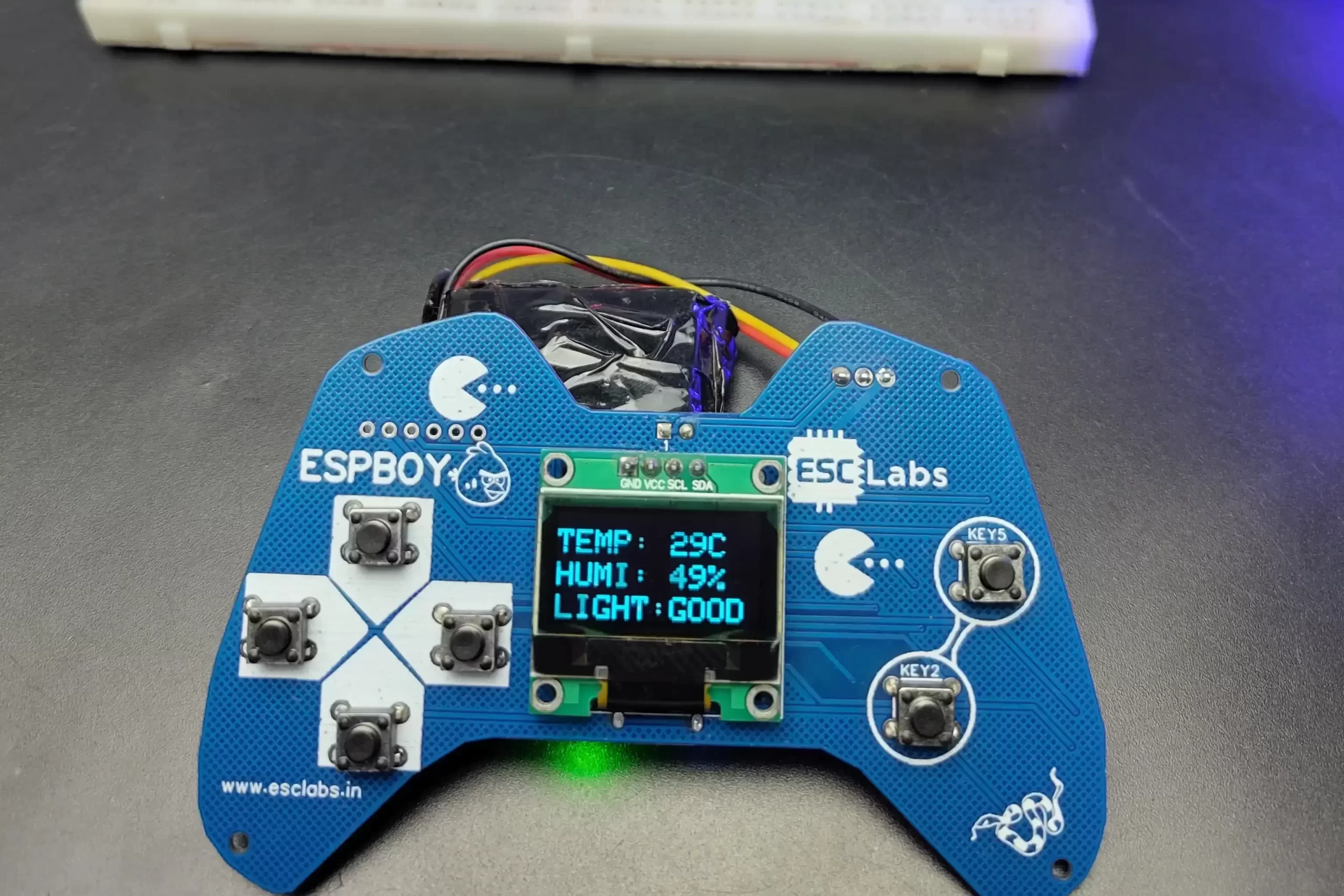
void printIncomingMessage(){
// Display Readings in Serial Monitor
//IN
Serial.println("INCOMING MESSAGES");
Serial.println(IN_button_state);
display.clearDisplay();
display.setTextSize(2);
display.setTextColor(WHITE);
display.setCursor(10, 20);
display.println("LIGHT: ");
display.setCursor(80, 20);
display.println(IN_button_state);
display.display();
delay(10);
}
void loop() {
//Get DHT readings
getReadings();
//Set values to send
outgoingmsg.button = OUT_button_state;
// Send message via ESP-NOW
esp_now_send(broadcastAddress, (uint8_t *) &outgoingmsg, sizeof(outgoingmsg));
printIncomingMessage();
}
Leave a comment