


India faces significant challenges related to air pollution, with several cities consistently ranking among the most polluted in the world. Among these, a few stand out as particularly affected by high levels of air pollutants. One such city is New Delhi, the capital of India. New Delhi has gained notoriety for its severe air quality issues, especially during the winter months. The primary contributors to air pollution in the city include industrial processes, vehicle emissions, the burning of fossil fuels industrial/construction dust, and the burning of agricultural residues in neighboring states. The combination of these factors leads to elevated levels of nitrogen dioxide (NO2), sulfur dioxide (SO2) and carbon monoxide (CO). These are the gases which are responsible for acid rain and other severe causes.

The consequences of this air pollution are dire, affecting the health of millions of residents. Respiratory problems, cardiovascular diseases, and other related ailments have become increasingly prevalent. Vulnerable populations, such as children and the elderly, are particularly at risk.
We can’t stop this pollution with just one click or one step. But we can reduce this by various methods like recycling plastic materials, using electric vehicles etc. By the way, the pollutants are still in the atmosphere. Sometimes the levels of pollutants go high over the critical level. We can’t sense or predict the levels if we are exposed to that air that will cause badly to our health, especially for children.

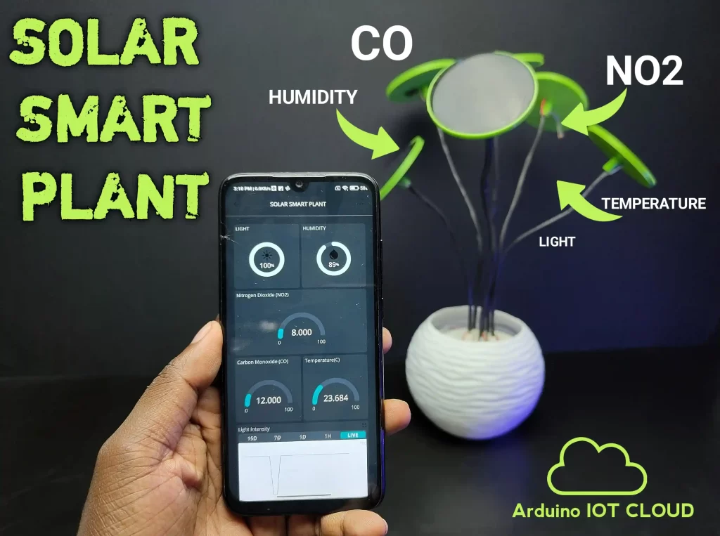
So, in this project, I am making a solar smart plant aiming to solve some of these problems. With this solar plant, we can detect/monitor the environmental conditions through our smartphones and computers. Which includes atmospheric levels of carbon monoxide, and nitrogen dioxide. In addition, we can monitor light intensity, temperature, and humidity. The plant has inbuilt lithium-ion batteries which automatically recharge using solar energy, also it has a deep sleep mode, so we don’t want to care about power issues.
Features and Applications of Solar Smart Plant

- We can place this plant outside of our home and we can monitor the air, we can monitor carbon monoxide and nitrogen dioxide. If it is high, we can either stay inside or we can use gas masks and take other safety precautions.
- The pot color will change to red if any parameters exceed the Hazzard level (we can program that)
- Can be used a garden/greenhouse monitoring, with the help of inbuilt temperature, humidity and light sensors we can monitor these parameters.
- It’s an artificial plant so we can use it as a decorative item (white color led will automatically turn on during nighttime)
Theory and Working of the Solar Smart Plant
The working of this solar smart plant is very simple. The idea is to read the environmental parameters like carbon monoxide, nitrogen dioxide, temperature, humidity and light. Then using a microcontroller these data will uploaded to a cloud service and we can monitor that data from anywhere in the world. Here I plan to use the ESP12E as the microcontroller because it has lots of pins for our application and also it has Wi-Fi and sleep mode capability. I used Arduino iot cloud for remote monitoring because Arduino iot cloud is very simple to use and 100% free. We can use solar panels to charge the battery with the help of a proper charging circuit. We can arrange the solar panels like branches of a plant, and we can place the sensors below the panel. So, the overall look will be like a plant with solar leaves.
Material Needed for Making the Solar Smart Plant
- ADP1706ARDZ-3.3-R7(3.3V regulator) – 1nos
- LTC4054ES5-4.2(li-ion Battery Charging Module) -1nos
- AHT20- (Temperature and Humidity sensor)-1nos
- Dfrobot Mems Carbon monoxide sensor-1nos
- Dfrobot Nitrogen dioxide sensor-1nos
- ESP12E-1nos
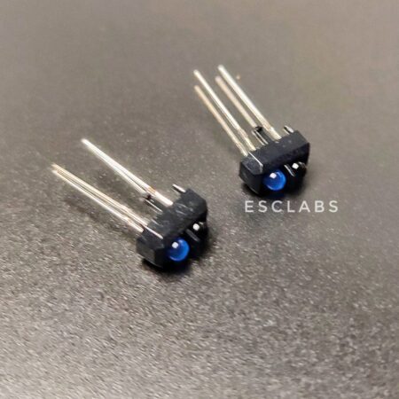
- LDR-1nos
- 74HC4051 Multiplexer-1nos
- 3MM LED -1nos
- WS2812B Neo pixel – 5nos
- ON/OFF Switch-1nos
- 10K Resistor-1nos
- 330ohm Resistor-1nos
- K Resistor-1nos
- 10uf Capacitor-2nos
- 100nf Capacitor-1nos
- 3.7v li-ion battery 18650 battery-4nos
- 5v 80mA Solar panel-6nos
- ESP12E breakout board-1nos
- 8pin SOIC breakout board-1nos
- 16pin SOIC breakout board-1nos
- 2pin JST female connector-2nos
- 2pin JST male connector-2 nos
- 3pin JST female connector-2nos
- 3pin JST male connector-2 nos
- Male header pins(strip) -1nos
- Female header pins(strip)-1nos
- Aluminium/copper wire-2meter
- Heat shrink tubes-2meter.
- Plant pot (readymade/3d printed)-1nos.
- 3D printed parts.

I bought the voltage regulator and battery charging IC from Digikey.in. The Carbon Monoxide (CO) sensor, Nitrogen Dioxide (NO2), temperature and humidity sensor were bought from dfrobot.com. All other components I purchased from Amazon.in. You can find all the purchase links in the BOM file on my project GitHub page. Here are the details of important components.
ESP12E Microcontroller
The ESP12E is a module based on the ESP8266 microcontroller, which is designed for wireless communication and Internet of Things (IoT) applications. It features the ESP8266 chip, which integrates a 32-bit Tensilica microcontroller, and Wi-Fi connectivity, and it has 1 analog pin and 16 digital IO pins. This is suitable for our application.
ADP1706ARDZ-3.3-R7(3.3V regulator)

The ADP1706 is a CMOS, low dropout linear regulator that operates from 2.5 V to 5.5 V and provides up to 1 A of output current. Using a proprietary architecture, they provide high power supply rejection and achieve excellent line and load transient response with a small 4.7 µF ceramic output capacitor. I am using this to convert the battery voltage(3.7v) into 3.3v(working voltage of esp12e).
LTC4054ES5-4.2(li-ion Battery Charging Module)

The LTC4054 is a complete constant-current/constant-voltage linear charger for lithium-ion batteries. Its Thin SOT package and low external component count make the LTC4054 ideally suited for our application.
Dfrobot Nitrogen dioxide sensor

MEMS NO2 sensor employs state-of-the-art microelectromechanical system (MEMS) technology, endowing the sensor with compact dimensions (13x13x2.5mm), low power consumption (<20mA), minimal heat generation, short preheating time, and swift response recovery. The sensor can qualitatively measure the concentration of nitrogen dioxide gas and is suitable for nitrogen dioxide detectors.
AHT20- (Temperature and Humidity sensor)

The AHT20 is a high-precision but low-cost temperature and humidity sensor, which is equipped with an improved MEMS semiconductor capacitive humidity sensor element. It features a standard I2C interface and a wide voltage supply of 2V-5V. With the simple peripheral circuit, it performs stably even in harsh environments in the measuring range of -40℃ ~ +85℃.
Dfrobot Mems Carbon monoxide sensor

MEMS Carbon Monoxide CO Gas Detection Sensor employs state-of-the-art microelectromechanical system (MEMS) technology, endowing the sensor with compact dimensions (13x13x2.5mm), low power consumption (<20 mA), minimal heat generation, a short preheating time, and swift response recovery. The sensor can measure carbon monoxide gas concentrations qualitatively.
74HC4051 8-Channel Analog Multiplexer/Demultiplexer
We have 3 analogue sensors and esp12e has one analog input. To read the 3 analog sensor data we need a multiplexer and I choose 74HC4051.
74HCT4051 is a single-pole octal-throw analogue switch (SP8T) suitable for use in analogue or digital 8:1 multiplexer/demultiplexer applications. The switch features three digital select inputs (S0, S1, and S2), eight independent inputs/outputs (Yn), a common input/output (Z) and a digital enable input (E). When E is HIGH, the switches are turned off.
Circuit Diagram of Solar Smart Plant

Here is the circuit diagram. The working of this circuit is as follows. The AHT20 sensor is an I2C sensor so I connected the SDA and SCL pins of the sensor to the SDA and SCL pins of ESP12E. Then we have 3 analog sensors (CO, NO2 and LDR). I have connected these sensors to the multiplexer(because esp12e has only one analog input), the control pins of the multiplexer I have connected to the digital pins of the ESP and the output pin to the A0 pin of esp12E. So we can read the data of each sensor one by one. I have added the complementary components for esp12e, voltage regulator and li-ion battery charger for proper working. Here we have LTC4054ES5 IC for charging the li-ion batteries. The output of battery charger is directly connected to the li-ion battery pack (4*3.7li-ion batteries). we have a total of 6 solar panels and each of them can deliver 80mA. So the total current is about 480mA when the panel is in parallel connection. In the circuit I have connected the input of The Li-ion battery charger to the output of solar panel. Then the regulator converts the 3.7v to 3.3v and feeds to the microcontroller. Download the circuit from here.
Building the Circuit of Solar Smart Plant on Dot PCB

Most of the components used in this circuit are SMD. I have already designed a PCB for this but that took some time to arrive here. To build the circuit on a common PCB we need to use a breakout board for the SMD ICs. I used readymade breakout boards for ESP12E, ADP1706 and 74HC4051. However, I failed to find a breakout board for the LTC4054 charging IC.

So first I made a simple breakout for the LTC4054 IC using a common PCB. For that first I cut a small piece of common PCB and inserted male pins into it (refer to images). Then I soldered single-stranded copper wire to every pin of the IC and connected those wires to the header pins.


After soldering all the SMD ICs to the breakout boards, I placed and soldered female header pins on the common PCB for placing the breakout boards. Then I soldered all other components to the PCB. I added JST connectors for the Solar panel, and battery here is the finished PCB.

I have tested the voltage regulator and battery charger IC in breadboard. I have adjusted some values and verified the circuits.

In the next step, I connected long wires (30CM) to the sensors because we are going to place the sensors on the downside of the so the solar panels. Also, I have connected long wires (30CM) for the solar panels.

I connected the batteries in parallel. I used old 3.7v li-ion batteries, each of them having a capacity of 2500mah so the total capacity of 10000mah.
3D Designing and Printing


To give a proper finish and look I designed a a base for each solar panel. This base will act as support and also I added a holder to hold the aluminium wire. I designed it using tinkercad and I printed it using my Ender 3v2 printer. I used green colour PLA with 20% infill for printing, which is more resembles a plant. Also, I designed and printed a base for holding all the stems together.
Download the .stl files from here
Building The Solar Smart Plant

After printing and making all parts let’s start the final assembly.

In the first step, I placed the solar panels on the 3D-printed base and inserted the wires through the hole.

Then I placed the sensors on the downside of the 3D-printed part using some glue.

In the next step, I inserted the aluminium wire into the 3D-printed part.

After that, I inserted all the wires including the aluminium wire into heat shrinking tube and applied heat. Now our first branch is ready.

I repeated the same process for all six solar panels and made six branches. Four of them have sensors on them.


After doing this I inserted all the stems and wires on the base plate and secured them with some glue.

Then I arranged the branches like a plant. Finally, I joined all the solar panel wires in parallel and connected a 2-pin male JST connector. Next, I placed the switch on the stem base and connected the battery pack serially with the switch.

Next, I inserted the battery pack in the pot and connected the battery pack, solar panel, neo pixel and sensors to the main board. After connecting all the wires to the main circuit board, I inserted the circuit board inside the pot. To fix the stem base to the pot I used a rigid 10cm pipe piece (you can use similar), so I glued the pipe to the stem base. Next glued the neo pixel strip to the pipe piece and finally, I fixed the pipe to the pot.
Arduino IoT Cloud Setup
To monitor the sensor data through mobile phones and smartphones we need to use some sort of cloud setup. I choose Arduino IoT cloud, the reason for selecting Arduino IoT cloud is as follows.
- Most of the features are free.
- Faster than other cloud platforms
- Easy programming
- Nice and clean UI
- IoT remote application is available for mobile phones.

We need to create an account in Arduino IoT Cloud to use the features that go to Arduino IoT cloud and login/sign up with your email ID. We need to create a thing on iot cloud for that Click on thing and click create. Then name the thing here I named a solar smart plant.

Then click on add cloud variables. These variables are for storing our data. In our case, we need to store light intensity, temperature, humidity, carbon monoxide level and nitrogen dioxide levels.

So first I click on add variable and name the variable then select the variable type as int variable for storing the light intensity value. Now select the read-only option and change the update duration to 10 seconds finally, click on add variable.

In the same way, I have added two float variables and two int variables for temperature humidity, carbon monoxide and nitrogen dioxide. These variables will store our sensor data.

The next step is to set up the device. So click on select the device and click on setup new device then select third-party device because we are using esp12e. From the menu device type menu select esp8266 and then select Node MCU. Also name the device.

Next, let’s set up the network credentials. Here we need to give the SSID and password of the Wi-Fi. Now system will generate a secret key for our project. We should download the pdf copy of that in case we forget/lose the key we can use the pdf.

To display these variable values, we need a dashboard so let’s set up the dashboard. For that go to the dashboard and click on Create Dashboard then name the dashboard, I named as Solar Smart Plant. Click on Add to select a widget, we have a lot of options to display the values in different styles. First, I selected the percentage widget. You can name the widget as you wish, I am going to use this widget to display the light intensity, so I named the widget as light intensity. Now click on the link variable and select the previously created int variable (light). We can select icon and the color-changing feature if we want, that is we can set a value to change color for example if the value goes below 50, we can set the color to change to red. after selecting these we are done with the first widget. I did the same for humidity.

To display temperature, I used the gauge widget. First, I changed the name to temperature, and I selected the temperature variable. Also, I selected the same gauge widget for carbon monoxide and nitrogen dioxide.

To display more scientifically and visualize properly I have also added chart widgets for light, CO and NO2. With this chart widget, we can see the live variation and previous values. After adding widgets and assigning variables to widgets we can set the dashboard view for desktop and mobile phones. For that Click on the arrange widget icon then we can drag, resize and arrange icons. that’s it.
Arduino Programming of Solar Smart Plant
Before finalizing the code, I interfaced each sensor individually with Arduino and verified the working. Then I combined the code and finalized it. Here I am explaining the workings of the code, also you can download the complete code from below.

First, go to the sketch tab of the Arduino IoT cloud, there we can see the automatically generated Arduino code. The code generated by the Arduino IoT cloud is not complete it gives the structure of the entire Arduino program. Either we edit the code in the iot cloud, or we can use the offline IDE. I am using an offline IDE for that I downloaded the code from the IoT cloud. For that Click on the three dots and select the download sketch option. Now you will get a.zip file, unzip the file and open the Arduino code for editing. It contains 2 more header files called Arduino secrets.h and thingproperties. h.
#include "arduino_secrets.h"
#include "thingProperties.h"
#include <DFRobot_AHT20.h>
#include <FastLED.h>
The sketch started with the header files and Arduino secrets. h and thing properties.h is used for providing the network credentials and variables for the Arduino IoT cloud. Then I added the DFrobot_AHT20 Library to read the aht20 sensor and fastled.h for controlling the neopixel. You can add these libraries from Arduino IDE itself. For that go to sketch -include library – manage library now search and install those libraries.
int s0 = 0;
int s1 = 2;
int s2 = 15;
int Z_pin = A0; //mux
#define NUM_LEDS 5
#define DATA_PIN 13

DFRobot_AHT20 aht20;
CRGB leds[NUM_LEDS];
Then I declared the pins for multiplexer, and neopixel LED and also declared the type of sensor and number of LEDs. We don’t want to declare the integers for storing the data of sensors because of the thingproperties.h files have all the information.
pinMode(s0, OUTPUT);
pinMode(s1, OUTPUT);
pinMode(s2, OUTPUT);
digitalWrite(s0, LOW);
digitalWrite(s1, LOW);
digitalWrite(s2, LOW);
aht20.begin();
initProperties();
ArduinoCloud.begin(ArduinoIoTPreferredConnection);
setDebugMessageLevel(2);
ArduinoCloud.printDebugInfo();
FastLED.addLeds<NEOPIXEL, DATA_PIN>(leds, NUM_LEDS);
In the setup section, I defined the pins of the multiplexer as output, and I first set these pins to low. Also started the AHT20, neopixel and Arduino IoT cloud communications.
 ArduinoCloud.update();
  if(aht20.startMeasurementReady(/* crcEn = */true))
  humidity=aht20.getHumidity_RH();
  temperature=aht20.getTemperature_C();
  delay(10);
  light=map(readMux(0),5,1024,0,100);
  carbon_Monoxide=map(readMux(1),10,600,0,100);
  nitrogen_Dioxide=map(readMux(2),10,600,0,100);
  delay(100);
  if(light<50)
  {
 for (int i = 0; i <5; i++) {
      leds[i] = CRGB::White;
      FastLED.show();
      delay(50);
  }
  }
       if(carbon_Monoxide>50||nitrogen_Dioxide>50||temperature>30)
       {
        for (int i = 0; i <5; i++) {
      leds[i] = CRGB::Red;
      FastLED.show();
      delay(50);
  }
  }
  if(carbon_Monoxide<50&&nitrogen_Dioxide<50&&temperature<30&&light>50)
       {
        for (int i = 0; i <5; i++) {
      leds[i] = CRGB::Black;
      FastLED.show();
      delay(50);
  }
  }
In the loop section, I have added ArduinoCloud.update(); This line is for updating the Arduino Cloud this will update the Arduino IoT cloud with new data in certain intervals.
if(aht20.startMeasurementReady(/* crcEn = */true))
This line will check if the AHT20 sensor is ready to start a new measurement. If true, it proceeds to read the humidity and temperature using humidity = aht20.getHumidity_RH() and temperature = aht20.getTemperature_C(). These values will directly go to the humidity and temperature variables.
light = map(readMux(0), 5, 1024, 0, 100); this will read the light value from the multiplexer (channel 0) and map it from the range of 5 to 1024 to a new range of 0 to 100. Since we are reading analog values the reading varies from 0-1024 according to the light intensity so we need to convert that to 0-100% that’s why I have used the map function here.
carbon_Monoxide = map(readMux(1), 10, 600, 0, 100); and nitrogen_Dioxide = map(readMux(2), 10, 600, 0, 100); Reads values for carbon monoxide and nitrogen dioxide from the multiplexer Channels and maps them to the range of 0 to 100.
After reading and storing the sensor data I gave different conditions for turning on/off the neopixel LEDs.
To turn on the white colour neopixels at night I used this condition.
if(light < 50): Checks if the light value is less than 50. If true, it iterates over five LEDs, setting them to white and displaying them.
this is to warn the users by turning on red LEDs if carbon monoxide or Nitrogen dioxide or temperature exceeds the threshold.
(carbon_Monoxide > 50 || nitrogen_Dioxide > 50 || temperature > 30): Checks if carbon monoxide, nitrogen dioxide, or temperature exceeds certain thresholds. If true, it iterates over five LEDs, setting them to red and displaying them
if(carbon_Monoxide < 50 && nitrogen_Dioxide < 50 && temperature < 30 && light > 50): Checks if carbon monoxide, nitrogen dioxide, temperature, and light meet specific conditions. If true, it iterates over five LEDs, setting them to black (turning them off) and displaying them.
 int readMux(int channel){
  int controlPin[] = {s0, s1, s2};

  int muxChannel[3][3]={
    {0,0,0}, //channel 0
    {0,0,1}, //channel 1
    {0,1,0}, //channel 2


  };

  for(int i = 0; i < 3; i ++){
    digitalWrite(controlPin[i], muxChannel[channel][i]);
  }

  int val = analogRead(Z_pin);
 return val;
}
This Arduino code defines the function named readMux that reads from the multiplexer (mux) and returns the analogue value read.
int readMux(int channel){int readMux(int channel) This declares a function named readMux that takes an integer parameter channel and returns an integer.
int controlPin[] = {s0, s1, s2}; int controlPin[]: this is the array to store the control pins for the multiplexer. s0, s1 and s2 are the variables representing the control pins of the multiplexer.
int muxChannel[3][3]={
  {0,0,0}, //channel 0
  {0,0,1}, //channel 1
  {0,1,0}, //channel 2
};
int muxChannel[3][3]: is a 2D array representing the configuration of the multiplexer channels. Each row corresponds to a channel, and each column corresponds to a control pin (s0, s1, s2). The values in this array specify which combination of control pin states (LOW or HIGH) to use for each channel.
for(int i = 0; i < 3; i ++){
  digitalWrite(controlPin[i], muxChannel[channel][i]);
}
This is for loop iterating over the control pins (s0, s1, s2). It sets the states of these pins according to the configuration specified in muxChannel for the given channel. This configures the multiplexer to read from the desired channel.
int val = analogRead(Z_pin); this will read the analog value and store it in val.
return val; this line will return the read analogue value.
In summary, this function configures a multiplexer to read from a specified channel and returns the analog value read from the corresponding pin.
ESP.deepSleep(10e6)
Here I used this command to put the esp12e into deep-sleep mode. This will help us to reduce the power consumption of esp12e. In this command, 10e6 corresponds to 10000000 microseconds which is equal to 10 seconds. that is in this case ESP will sleep for 10 seconds. We can set this time from 1 microseconds to 71 minutes. After the set time ESP will wake send the data to the cloud and go back to sleep.
That’s all about the Arduino code of the solar smart plant. After complaining about the code I uploaded the code to the ESP12E. I used my homemade ESP12E programmer to upload the code to ESP12E, you can use any USB to TTL converter or FTDI breakout.
Final look and Working Video Demonstration

Here is the final look of the completed project.
Updation and Modifications
1. This project is ideal for town areas to monitor these data, in town areas Wi-Fi is easily accessible. But when you want to use it in non-wifi areas we can either use the sensor section in remote areas or we can send the data to the controller using Lora or espnow communication.
2. Also, we can use 2G GSM -based boards for uploading this data directly to the cloud.
3. As I said earlier we can print the PCB so this way we can decrease the total size.
4. We can change the sensors according to our applications. For example, we can set different Lora nodes to monitor soil moisture in different fields.
5. We can add a small OLED also to display the data, so we can monitor the data without using the smart phone.
You can download the Solar smart plant Project files using the given link. The links consists of circuit diagram, code and 3D model files which you can use to build your own solar smart plant.
Leave a comment